Motor rotor position obtaining method and system

A motor rotor and acquisition method technology, applied in control system, motor control, motor parameter estimation/correction, etc., can solve problems such as large error and difficult control, achieve system robustness suppression, reduce cost, improve The effect of power density

Active Publication Date: 2020-03-31
INST OF ELECTRICAL ENG CHINESE ACAD OF SCI
View PDF14 Cites 11 Cited by
  • Summary
  • Abstract
  • Description
  • Claims
  • Application Information

AI Technical Summary

Problems solved by technology

[0003] Therefore, the technical problem to be solved by the present invention is to overcome the shortcomings of the motor rotor position information acquisition method in the prior art, such as large error and difficult control, so as to provide a motor rotor position acquisition method and system

Method used


Image

  • Motor rotor position obtaining method and system
  • Motor rotor position obtaining method and system
  • Motor rotor position obtaining method and system

Examples


Embodiment 1

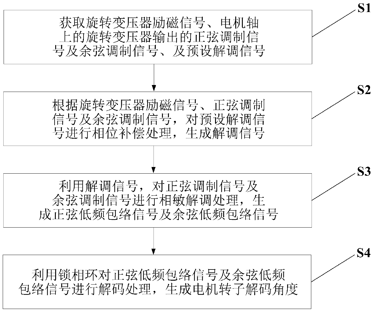
[0045] This embodiment provides a motor rotor position acquisition method, which is applied in the field of motor control, such as figure 1 shown, including the following steps:

[0046] Step S1: Obtain the excitation signal of the resolver, the sine modulation signal and the cosine modulation signal output by the resolver on the motor shaft, and the preset demodulation signal.

[0047] The output voltage of the resolver will change with the rotor angle, so in the motor control system, it is often used to obtain the rotor position of the motor. When an AC high-frequency voltage of a certain frequency is applied to the excitation winding of the resolver, the voltage amplitude of the output winding has a sine or cosine function relationship with the rotor rotation angle, or maintains a certain proportional relationship, or is linear with the rotation angle within a certain range of rotation angle. relation. The embodiment of the present invention uses the sine modulation signa...

Embodiment 2

[0137] This embodiment provides a motor rotor position acquisition system, such as Figure 24 shown, including:

[0138] The signal acquisition module 1 is used to acquire the resolver excitation signal, the sine modulation signal and cosine modulation signal output by the motor shaft resolver, and the preset demodulation signal; this module executes the method described in step S1 in Embodiment 1, and This will not be repeated here.

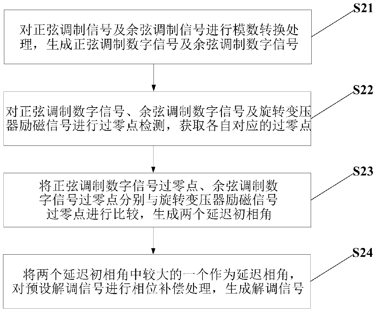
[0139] The demodulation signal generation module 2 is used to perform phase compensation processing on the preset demodulation signal according to the resolver excitation signal, the sine modulation signal and the cosine modulation signal to generate the demodulation signal; this module executes the step S2 in the embodiment 1. The method described will not be repeated here.

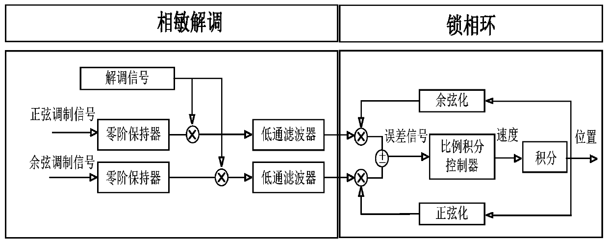
[0140] The envelope signal generating module 3 is used to utilize the demodulation signal to carry out phase-sensitive demodulation processing on the sine modulation sig...

Embodiment 3

[0144] An embodiment of the present invention provides a computer device, such as Figure 25 As shown, it includes: at least one processor 401 , such as a CPU (Central Processing Unit, central processing unit), at least one communication interface 403 , memory 404 , and at least one communication bus 402 . Wherein, the communication bus 402 is used to realize connection and communication between these components. Wherein, the communication interface 403 may include a display screen (Display) and a keyboard (Keyboard), and the optional communication interface 403 may also include a standard wired interface and a wireless interface. The memory 404 may be a high-speed RAM memory (Ramdom Access Memory, volatile random access memory), or a non-volatile memory (non-volatile memory), such as at least one disk memory. Optionally, the memory 404 may also be at least one storage device located away from the aforementioned processor 401 . Wherein, the processor 401 can execute the meth...


PUM


Abstract

The invention discloses a motor rotor position collection method and system. The method comprises the following steps: acquiring a rotary transformer excitation signal, a sine modulation signal and acosine modulation signal output by a rotary transformer on a motor shaft, and a preset demodulation signal; performing phase compensation on a preset demodulation signal according to the rotary transformer excitation signal, the sine modulation signal and the cosine modulation signal to generate a demodulation signal; performing phase-sensitive demodulation processing on the sine modulation signaland the cosine modulation signal by using the demodulation signal to generate a sine low-frequency envelope signal and a cosine low-frequency envelope signal; and decoding the sine low-frequency envelope signal and the cosine low-frequency envelope signal by using a phase-locked loop to generate a motor rotor decoding angle. The phase-sensitive demodulation method and the phase-locked loop are used for tracking the position of the motor rotor in real time, accurate position information is provided for motor driving, the decoding precision is improved, and the decoding speed is increased; phase compensation is performed on the preset demodulation signal so that the situation of failure of the method caused by phase lag can be avoided.

Description

technical field [0001] The invention relates to the technical field of motor control, in particular to a method and system for acquiring the position of a motor rotor. Background technique [0002] New energy vehicles have the advantages of high energy utilization efficiency, clean and pollution-free, and simple structure, and have been widely developed and used all over the world. Permanent magnet synchronous motors are widely used in the new energy automobile industry, and their control systems often use rotor flux linkage oriented vector control. The detection accuracy of the rotor position directly affects the performance of the control system. As a position sensor, the resolver has the advantages of high reliability, shock resistance, humidity resistance, and is suitable for harsh workplaces. It is widely used in permanent magnet synchronous motor control systems. The reluctance resolver has a simple structure and only contains copper. Wires and silicon steel sheets ar...

Claims


Application Information

Patent Timeline
Patent Type & Authority Applications(China)
IPC IPC(8): H02P23/14
CPCH02P23/14H02P2207/05
Inventor 刘忠永李琦何国林范涛温旭辉
Owner INST OF ELECTRICAL ENG CHINESE ACAD OF SCI
Why Eureka
Try Eureka