Arsenic removal method of waste SCR denitration catalyst and preparation method of regenerated powder of waste SCR denitration catalyst

A denitration catalyst and oxidant technology, applied in catalyst regeneration/reactivation, chemical instruments and methods, physical/chemical process catalysts, etc., can solve the problems of incomplete removal of arsenic, inability to react with strong alkaline solution, etc., and achieve obvious arsenic removal effect. , the effect of low arsenic content and simple operation

Pending Publication Date: 2020-04-24
中节能生态环境科技有限公司 +1
View PDF2 Cites 3 Cited by
  • Summary
  • Abstract
  • Description
  • Claims
  • Application Information

AI Technical Summary

Problems solved by technology

It has been reported that the arsenic in spent denitrification catalysts is mainly As 2 o 3 and As 2 o 5 Two forms exist, although both forms of arsenic can react with stro

Method used


Image

  • Arsenic removal method of waste SCR denitration catalyst and preparation method of regenerated powder of waste SCR denitration catalyst
  • Arsenic removal method of waste SCR denitration catalyst and preparation method of regenerated powder of waste SCR denitration catalyst
  • Arsenic removal method of waste SCR denitration catalyst and preparation method of regenerated powder of waste SCR denitration catalyst

Examples


Embodiment 1

[0061] A method for removing arsenic from a waste SCR denitrification catalyst, characterized in that it comprises the following steps:

[0062] (1) Pretreatment

[0063] The waste SCR denitration catalyst is sequentially cleaned, crushed and wet-grinded to obtain a slurry; the solid-to-liquid ratio of the slurry is 1:3;

[0064] (2) oxidation treatment

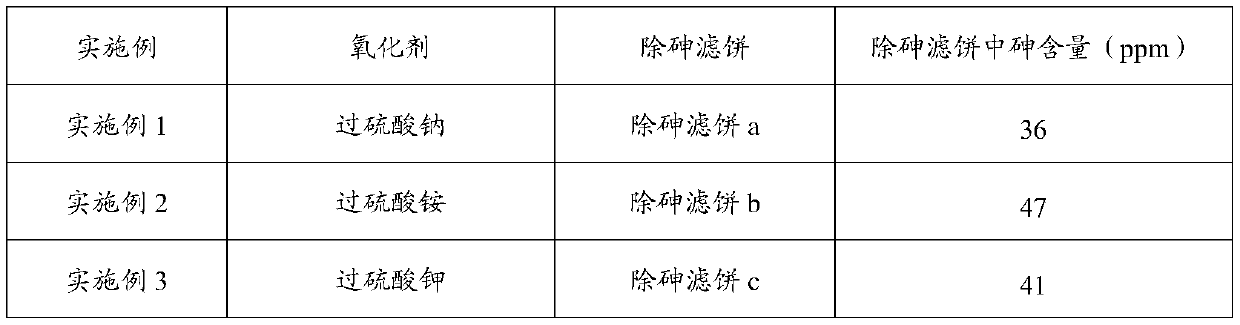
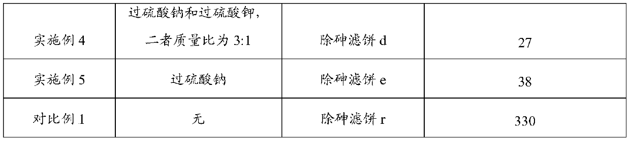
[0065] Adding an oxidant solution to the slurry obtained in step (1) to carry out an oxidation reaction to obtain the oxidized slurry; the oxidation reaction is carried out in a regeneration reactor; the oxidant is sodium persulfate; the addition of the oxidant solution The amount is such that in the mixed material of the slurry and the oxidant solution, the solid-to-liquid ratio is 1:4; the concentration of the oxidant solution is 2wt%; the reaction conditions of the oxidation reaction are: under stirring, at 20°C Reaction at reaction temperature for 0.5h;

[0066] (3) Alkali leaching treatment

[0067] Add a strong alka...

Embodiment 2

[0079] Compared with embodiment 1, only following difference:

[0080] The oxidizing agent is ammonium persulfate, and the arsenic-removing filter cake b is obtained.
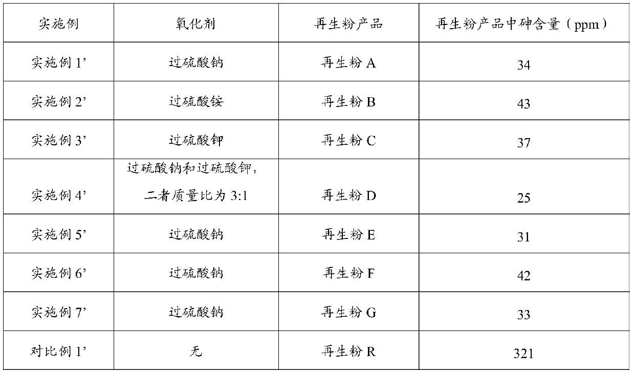
[0081] Example 2'

[0082] Compared with embodiment 1', only following difference:

[0083] It was carried out on the basis of Example 2 to obtain recycled powder B.

Embodiment 3

[0085] Compared with embodiment 1, only following difference:

[0086] The oxidizing agent is potassium persulfate, and the arsenic-removing filter cake c is obtained.

[0087] Example 3'

[0088] Compared with embodiment 1', only following difference:

[0089] It was carried out on the basis of Example 3 to obtain recycled powder C.


PUM


Abstract

The invention provides an arsenic removal method in the regeneration process of an SCR denitration catalyst, wherein the method comprises the following steps: (1) pretreatment: sequentially carrying out cleaning, crushing and wet grinding treatment on a waste SCR denitration catalyst to obtain slurry; (2) oxidation treatment: adding an oxidant solution into the slurry, and carrying out oxidation reaction to obtain oxidized slurry; (3) alkaline leaching treatment: adding a strong alkaline solution into the oxidized slurry, and carrying out alkaline leaching reaction to obtain alkaline-leached slurry; and (4) filtering and cleaning: sequentially filtering and cleaning the alkaline leached slurry to obtain an arsenic removal filter cake. The arsenic removal method is obvious in arsenic removal effect, low in energy consumption, simple to operate and low in operation cost. The invention further provides a preparation method of SCR denitration catalyst regenerated powder. The preparation method comprises the arsenic removal method. According to the preparation method, arsenic in the waste SCR denitration catalyst can be well removed, so that the arsenic content in the prepared SCR denitration catalyst regenerated powder meets the requirement.

Description

technical field [0001] The invention belongs to the field of resource utilization of solid and hazardous waste, in particular to a method for removing arsenic of an SCR denitrification catalyst and a method for preparing regenerated powder. Background technique [0002] In August 2014, the Ministry of Environmental Protection officially issued the "Notice on Strengthening the Supervision of Waste Flue Gas Denitrification Catalysts" and "Guidelines for Examination of Hazardous Waste Operation Permits for Waste Flue Gas Denitrification Catalysts", which included waste flue gas denitrification catalysts (vanadium-titanium series) Hazardous wastes are managed and classified as "HW49 Other Wastes" in the "National Hazardous Waste List" (the latest regulations are changed to HW50). [0003] SCR denitrification catalysts (that is, power plant denitrification catalysts) are usually installed in a "2+1" installation mode. The normal SCR denitrification catalyst service life is about ...

Claims


Application Information

Patent Timeline
IPC IPC(8): B01J38/48B01J38/64B01J38/60C22B30/04C22B3/12C22B3/22C22B3/44
CPCB01J38/48B01J38/64B01J38/60C22B30/04C22B3/12C22B3/22C22B3/44Y02P10/20
Inventor 刘东风李彬彬施耀华刘洪兴张蕊宋越薛镜徽吴磊邓丹丹张博陈振华邱晨蔡增宅邹良栋
Owner 中节能生态环境科技有限公司
Why Eureka
Try Eureka