Micro gas turbine
A micro gas turbine and gas compressor technology, which is applied in gas turbine devices, combustion chambers, combustion methods, etc., can solve the problems of heat loss along the process, poor stability of the rotor system, large axial force of the rotor, etc., and achieve convenient maintenance and stable switching Reliable, highly selective effects
- Summary
- Abstract
- Description
- Claims
- Application Information
AI Technical Summary
Problems solved by technology
Method used
Image
Examples
Embodiment 1
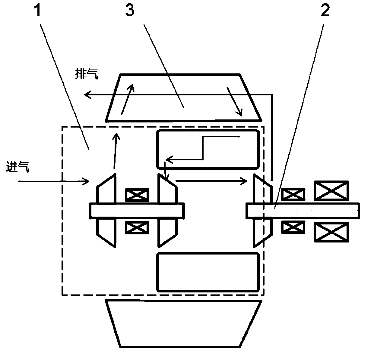
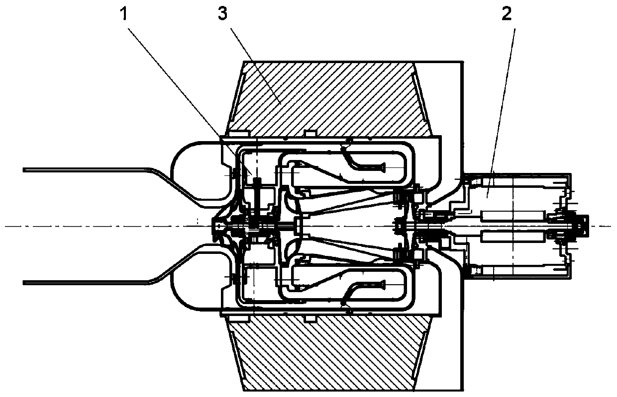
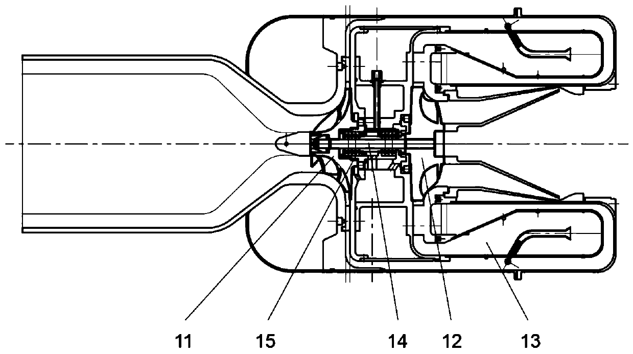
[0075] like figure 1 , 2 , 3, and 4, this embodiment provides a micro gas turbine with a regenerator, which has a high-pressure machine 1, a low-pressure machine 2 and a regenerator 3, and the high-pressure machine 1 includes a compressor 11, a high-pressure turbine 12, and a combustion chamber 13 , the first rotating shaft 14, the high-pressure bearing group 15, the low-pressure machine 2 includes a low-pressure turbine 21, a motor 22, a low-pressure bearing group 24, a second rotating shaft 23, and a flue gas chamber 25, and the regenerator 3 has a first inlet 31 and a first outlet 32 , a second inlet 33 , and a second outlet 34 .
[0076] In this embodiment, the compressor 11 and the high-pressure turbine 12 are coaxially and fixedly installed back-to-back on the first rotating shaft 14, the intake end of the compressor 11 communicates with the outside world, the exhaust end communicates with the first inlet 31 of the regenerator, and the regenerator The first outlet 32 ...
Embodiment 2
[0086] The difference between this embodiment and Embodiment 1 is that, as Figure 5 As shown, the regenerator 3 in this embodiment is also provided with a third inlet 35 and a third outlet 36. The third inlet 35 and the third outlet 36 form a third passage, and the third passage is connected with the first passage and the second passage. Channels are not connected.
[0087] In this embodiment, the exhaust end of the high-pressure turbine 12 is also communicated with the third inlet 35 of the regenerator, and the third outlet 36 of the regenerator is communicated with the intake end of the low-pressure turbine 21, and the gas at the exhaust end of the high-pressure turbine 12 is After the heat exchange cools down, it enters the low-pressure turbine 21.
[0088] In this embodiment, due to the high conversion rate of the low-pressure turbine 21, the high-temperature gas at the outlet of the combustion chamber 13 can first enter the regenerator 3 for heat exchange, and then be e...
Embodiment 3
[0090] In this embodiment, a rotor system for the above-mentioned gas turbine low-pressure machine 2 is provided.
[0091] In this rotor system, it includes a turbine shaft for installing the low-pressure turbine 21 and a motor shaft for installing the motor 22. The turbine shaft and the motor shaft are connected by a coupling to form a second rotating shaft 23. Between the low-pressure turbine 21 and the motor shaft A first bearing 241 and a second bearing 242 are arranged between the couplings, and the motor shaft and the motor body are rotationally connected through a third bearing 243 and a fourth bearing 244 .
[0092]The low-pressure turbine 21 has a longer wheelbase, and the low-pressure turbine 21 is connected to the motor shaft through a coupling. In this way, the heat at the end of the low-pressure turbine 21 can be isolated, and the large axial thrust at the end of the low-pressure turbine 21 can be undertaken. Compared with connecting the low-pressure turbine 21 an...
PUM
 Abstract
Description
Claims
Application Information
 - R&D
- Intellectual Property
- Life Sciences
- Materials
- Tech Scout
- Unparalleled Data Quality
- Higher Quality Content
- 60% Fewer Hallucinations
Browse by: Latest US Patents, China's latest patents, Technical Efficacy Thesaurus, Application Domain, Technology Topic, Popular Technical Reports.
© 2025 PatSnap. All rights reserved.Legal|Privacy policy|Modern Slavery Act Transparency Statement|Sitemap|About US| Contact US: help@patsnap.com


