
Laser frequency stabilizing device and method and semiconductor laser assembly adopting laser frequency stabilizing device

A technology of semiconductors and lasers, which is applied in the field of laser frequency stabilization devices, can solve the problems of small central frequency adjustment range, non-universal applicability, and low operating frequency, and achieve easy adjustment, avoid temperature drift and residual amplitude modulation noise, and enhance The effect of stability

Active Publication Date: 2020-05-08
UNIV OF SCI & TECH OF CHINA
View PDF5 Cites 14 Cited by
  • Summary
  • Abstract
  • Description
  • Claims
  • Application Information

AI Technical Summary

Problems solved by technology

There are several existing schemes using the AOM, including using a voltage-controlled oscillator to drive the AOM, modulating the light through the atomic vapor chamber, and obtaining the absorption spectrum signal. The disadvantage is that the atomic absorption spectrum method can only be used for specific wavelengths, and cannot It is universal; use a specially designed AOM working in the Raman-Nath diffraction area, combined with a confocal cavity to obtain the PDH error signal, the disadvantage is that the operating frequency of this AOM is very low, only tens of MHz, and the center frequency adjustment range is small. Moreover, the product is only suitable for a specific band, not universal

Method used


Image

  • Laser frequency stabilizing device and method and semiconductor laser assembly adopting laser frequency stabilizing device
  • Laser frequency stabilizing device and method and semiconductor laser assembly adopting laser frequency stabilizing device
  • Laser frequency stabilizing device and method and semiconductor laser assembly adopting laser frequency stabilizing device

Examples


Embodiment Construction

[0044] In order to make the object, technical solution and advantages of the present invention clearer, the present invention will be further described in detail below in conjunction with specific embodiments and with reference to the accompanying drawings.

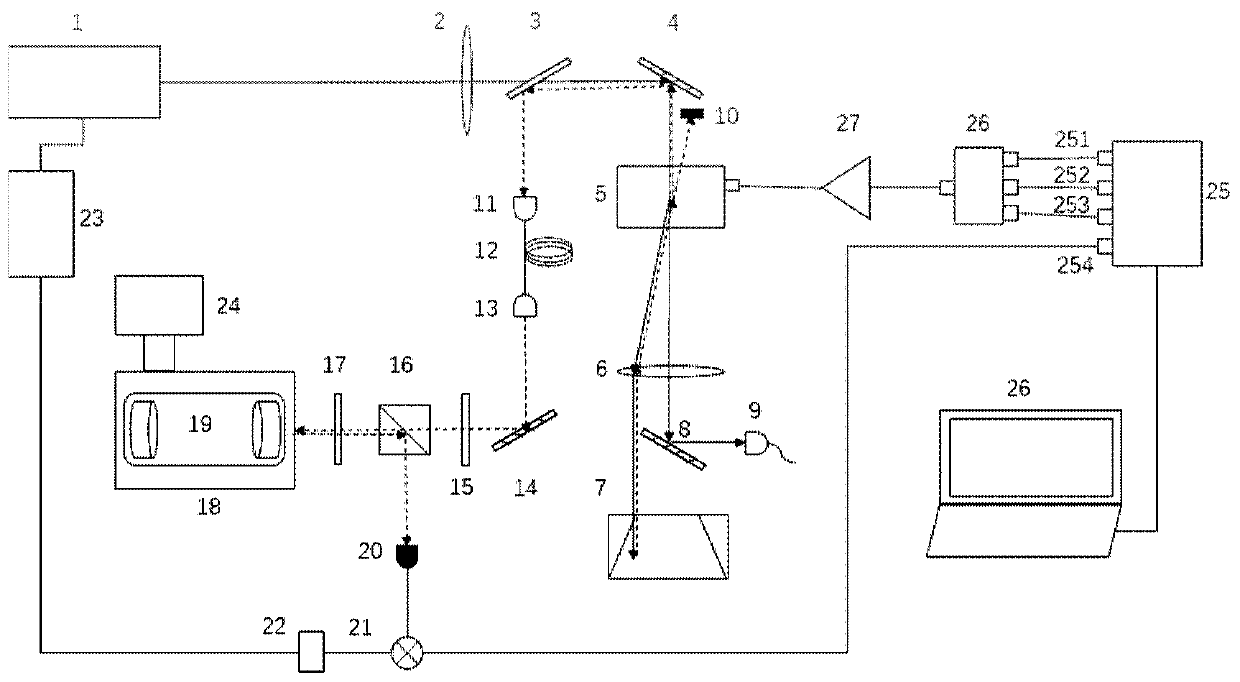
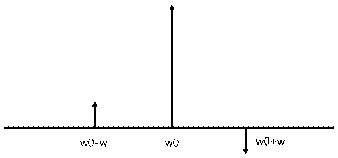
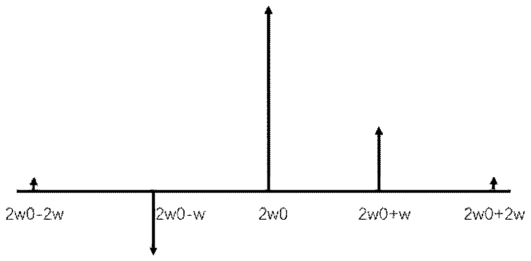
[0045] The invention discloses a laser frequency stabilization method and device, comprising a semiconductor laser, an acousto-optic modulator, a lens, a rectangular prism, a half glass slide, a polarization beam splitter, a quarter glass slide, and is arranged in a vacuum device Fabry-Perot cavity, multi-channel RF signal source, combiner, RF amplifier, photodetector, mixer, low-pass filter and servo system. Use multi-channel radio frequency signal source 25 to generate frequency respectively w 0 、w 0 -w,w 0 +w, RF signals with phases of 0 degrees, 0 degrees, and 180 degrees respectively, are amplified by the RF amplifier 27 to drive the acousto-optic modulator 5, and the laser light emitted by the semiconductor laser ...


PUM


Abstract

The invention discloses a laser frequency stabilizing device, comprises a semiconductor laser, an acoustic optical modulator, a Fabry-Perot cavity arranged in a vacuum device, a multi-channel radio frequency signal source, a combiner, a radio frequency amplifier, a photoelectric detector and a frequency mixer, wherein laser emitted by a semiconductor laser to be subjected to frequency stabilization generates +1 level or -1 level diffracted light after passing through the acousto-optic modulator for the first time, and the +1 level or -1 level diffracted light is reflected back to the acousto-optic modulator and generates +1+1 level or -1-1 level diffracted light after passing through diffraction for the second time; and the +1+1 level or -1-1 level diffracted light enters the Fabry-Perot cavity, a signal of the +1+1 level or -1-1 level diffracted light is reflected to the photoelectric detector, a detection electric signal and a demodulation signal of the multi-channel radio frequencysignal source are mixed and processed by a mixer to obtain an error signal, and the error signal is fed back to the semiconductor laser to realize frequency stabilization. According to the invention,the laser passes through the acousto-optic modulator twice to expand the frequency adjustment range, and the stability of the laser power in the frequency scanning process is further enhanced.

Description

technical field [0001] The invention relates to the field of laser frequency stabilization, in particular to a laser frequency stabilization device and method. Background technique [0002] Semiconductor lasers are lasers with narrow linewidth, easy tuning, small size, low power consumption, and long life. They are widely used in various fields such as laser communication, atomic frequency standards, quantum information, and laser printing. Since the laser frequency is easily affected by temperature, current, and vibration, the frequency stability of semiconductor lasers is very important. [0003] Common frequency stabilization methods for semiconductor lasers include PDH technology using ultra-stable Fabry-Perot cavity and saturable absorption spectroscopy technology. Among them, the advantage of saturated absorption spectroscopy technology is that it is convenient, simple, and low in cost, but it has a strict limitation on the laser wavelength. PDH technology is named a...

Claims


Application Information

Patent Timeline
Patent Type & Authority Applications(China)
IPC IPC(8): H01S5/068H01S5/0687
CPCH01S5/068H01S5/0687
Inventor 贺冉崔金明陈炎曹洹艾铭忠黄运锋李传锋
Owner UNIV OF SCI & TECH OF CHINA
Learn More