A kind of composite non-precious metal denitration catalyst and preparation method thereof

A denitrification catalyst and non-precious metal technology, which is applied in the field of composite non-precious metal denitrification catalyst and its preparation, can solve the problems of unsatisfactory catalytic efficiency, poor environmental protection, toxicity or pollution, etc., and achieve large binding force, stable performance, and reduce Effects of Toxic Pollution

Active Publication Date: 2021-02-09
SUZHOU TAONE SINCERE NANOMATERIAL TECH CO LTD
View PDF10 Cites 0 Cited by
  • Summary
  • Abstract
  • Description
  • Claims
  • Application Information

AI Technical Summary

Problems solved by technology

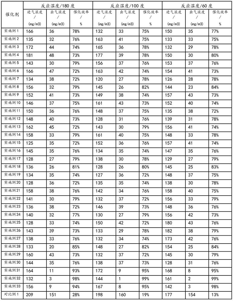
The above two catalysts can treat flue gas under the condition of less than 200 degrees, but the above two preparation methods will produce toxic or polluting substances, and the environmental protection is poor. At the same time, in the actual use of the catalyst, the catalytic efficiency is not very ideal

Method used


Image

  • A kind of composite non-precious metal denitration catalyst and preparation method thereof
  • A kind of composite non-precious metal denitration catalyst and preparation method thereof

Examples


Embodiment 1

[0033] A layer of catalyst layer is vapor-deposited on the zeolite by a vacuum coating machine, and the catalyst layer is Ti0 2 , which can be monocrystalline Ti0 2 , it can also be a mixed oxide in which multiple crystal forms coexist, such as rutile Ti0 2 and anatase Ti0 2 Mixing, in this embodiment, the catalyst layer is rutile Ti0 2 and anatase Ti0 2 mixed oxides, the thickness of which is 10nm; the parameters of evaporation conditions in the above process are as follows: the vacuum degree of the vacuum chamber is 4.9*10 -3 Pa, the temperature of the vacuum chamber is 200 degrees, the gas used is argon, the target material parameters: Ti0 2 Target material, 1mm particles, density 80%, purity 99.95%, electron gun current set to 100mA, deposition rate controlled at According to the XRD standard card comparison, after evaporation, the rutile TiO 2 :Anatase TiO 2 =6.1:1.0 (Wt%).

[0034] It should be noted that, in this embodiment, the zeolite is a Y-type zeolite mole...

Embodiment 2

[0036] Evaporate a catalyst layer on the electrospun nanofiber by vacuum coating machine, the catalyst layer is V 2 o 5 , with a thickness of 7nm; the parameters of evaporation conditions in the above process are as follows: the vacuum degree of the vacuum chamber is 4*10 -3 Pa, the temperature of the vacuum chamber is 250 degrees, the gas used is nitrogen, the target material parameters: V 2 o 5 Target material, 2mm particles, density 62%, purity 99.96%, electron gun current set to 200mA, deposition rate controlled at

[0037] In this embodiment, the electrospun nanofibers are nylon 6 electrospun nanofibers, and the BET specific surface area is 133 mg / m 3 .

Embodiment 3

[0039] A catalyst layer is vapor-deposited on the glass fiber by a vacuum coating machine, and the catalyst layer is Cr 2 o 3 , with a thickness of 5nm; the parameters of evaporation conditions in the above process are as follows: the vacuum degree of the vacuum chamber is 3*10 -3 Pa, the temperature of the vacuum chamber is 300 degrees, the gas used is argon, the target parameter: Cr 2 o 3 Target material, 3mm particles, density 82%, purity 99.95%, electron gun current set to 300mA, deposition rate controlled at


PUM

PropertyMeasurementUnit
specific surface areaaaaaaaaaaa
thicknessaaaaaaaaaa
thicknessaaaaaaaaaa

Abstract

The invention discloses a composite non-precious metal denitrification catalyst and a preparation method thereof, which are realized through the process of coating evaporation, no toxic or polluting substances will be produced in the whole process, and the whole process is environmentally friendly and clean; at the same time, the raw materials used are high-purity The target material does not need to be filtered to remove impurities such as nitrate and chloride ions during the preparation process, which not only reduces the toxic pollution of the catalyst by the above impurities, but also reduces the preparation steps, improves the activity of the catalyst and the utilization rate of raw materials, and improves the utilization rate. Reduced raw material usage.

Description

technical field [0001] The invention relates to the technical field of catalysts, in particular to a composite non-precious metal denitration catalyst and a preparation method thereof. Background technique [0002] With the continuous development of industrial technology, the environmental protection requirements for industrial technology are getting higher and higher, especially the requirements for the treatment of industrial flue gas, industrial waste gas and automobile exhaust, and the treatment standards are more stringent. In the field of flue gas denitrification, in order to make the final discharge of flue gas meet the standard, it is generally used to treat the flue gas with a denitrification catalyst and / or adding a reducing agent, such as in NH 3 -SCR technology, V 2 o 5 -WO X / TiO 2 It is the most commercially available denitrification catalyst today. The active window temperature is 300-400 degrees. However, the thermal stability of the catalyst is poor, and...

Claims


Application Information

Patent Timeline
Patent Type & Authority Patents(China)
IPC IPC(8): B01J29/08B01J31/36B01J23/26B01J27/24B01J23/75B01J23/755B01J29/76B01J29/14B01J27/051B01J27/22B01J37/02B01J37/34B01D53/56B01D53/86
CPCB01D53/8628B01D2258/0283B01J23/002B01J23/26B01J23/75B01J23/755B01J27/051B01J27/22B01J27/24B01J29/088B01J29/146B01J29/7607B01J31/36B01J37/0244B01J37/342
Inventor 钱若棨钱敬吉
Owner SUZHOU TAONE SINCERE NANOMATERIAL TECH CO LTD
Why Eureka
Try Eureka