
Optical fiber preform and preparation method thereof

A technology of optical fiber prefabricated rod and core rod, which is applied in the field of optical communication, can solve the problems of fiber attenuation, failure to reduce loss, and deterioration of bending performance, etc., and achieve the effects of large effective area, alleviating boundary effects, and reducing fiber loss

Pending Publication Date: 2020-06-23
ZHONGTIAN TECH ADVANCED MATERIALS CO LTD +1
View PDF16 Cites 5 Cited by
  • Summary
  • Abstract
  • Description
  • Claims
  • Application Information

AI Technical Summary

Problems solved by technology

[0002] As we all know, the attenuation and optical parameters of the optical fiber depend on the performance of the optical fiber preform. In order to obtain a large effective area, the main method is to reduce the core refractive index and increase the core diameter, but simply reduce the core refractive index and increase the core diameter. Although it is possible to increase the effective area of ​​the fiber, it is accompanied by an increase in the cut-off wavelength and deterioration of the fiber attenuation and bending performance, causing the fiber to exceed the relevant indicators.
Moreover, the pure silicon core design method requires complex viscosity matching inside, and the manufacturing process is extremely difficult.
In addition, in order to reduce the fiber loss, the Rayleigh scattering of the fiber can be effectively reduced by reducing the doping concentration of the fiber preform, but the Rayleigh scattering of the fiber is not only affected by the doping concentration, but also affected by the density fluctuation. Layer design is prone to cause mismatch between core and cladding, unable to improve Rayleigh scattering, and unable to reduce loss

Method used


Image

  • Optical fiber preform and preparation method thereof
  • Optical fiber preform and preparation method thereof
  • Optical fiber preform and preparation method thereof

Examples


preparation example Construction

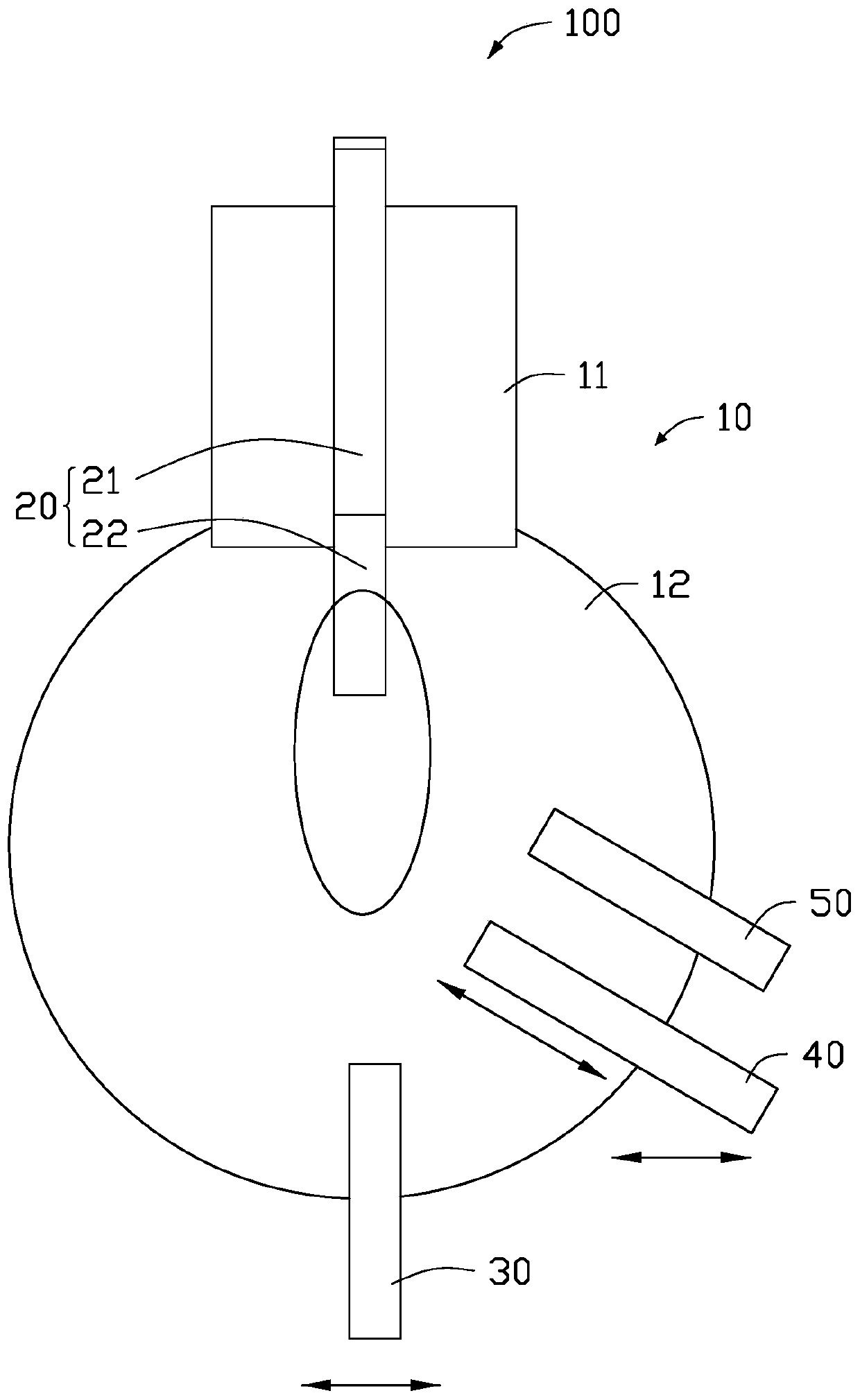
[0035] see Figure 4 , the present invention also provides a method for preparing an optical fiber preform, comprising the following steps:

[0036] Step S31, using a vapor deposition process to prepare a core rod, sequentially depositing through the first blowtorch, the second blowtorch and the third blowtorch, and injecting fluoride, silicon tetrachloride, combustible gas, inert gas and oxygen into the first blowtorch, Form the silicon dioxide loose body of fluorine element, pass oxygen, combustible gas, silicon tetrachloride, germanium tetrachloride and inert gas into the second torch, and form a core layer loose body on the surface of the silicon dioxide loose body. Oxygen, combustible gas, silicon tetrachloride and inert gas are fed into the three blowtorches to form a silicon dioxide inner cladding layer on the surface of the core layer loose body, and the core rod is obtained after the deposition is completed;

[0037] Step S32, performing dehydration and vitrification...

Embodiment 1

[0051] First, the angle of the first blowtorch is adjusted to 50°, the angle of the second blowtorch is adjusted to 40°, and SiF is introduced into the first blowtorch by vapor deposition. 4 、SiCl 4 、H 2 , KCl, Ar and O 2 , Ar as a carrier gas to bring KCl into the first blowtorch, wherein the flow of Ar is controlled at 60cc / min, SiF 4 The flow of gas is controlled at 100cc / min, and O is passed into the second blowtorch 2 、H 2 、SiCl 4 、GeCl 4 and Ar gas, where GeCl 4 The flow of gas is controlled at 50cc / min, and O is passed into the third blowtorch 2 、H 2 、SiCl 4 And Ar gas, deposited to form powder rods.

[0052] The deposited powder rods are dehydroxylated and vitrified and sintered in a sintering furnace. Among them, after the dehydration is completed and the glass transition temperature rises to 1250 °C, SiCl 4 Gas, the flow rate is 1g / min, the constant temperature time is 6h, and then SiF is introduced 4 Gas, the flow rate is 300cc / min, and the constant tem...

Embodiment 2

[0057] First, the angle of the first blowtorch is adjusted to 70°, and the angle of the second blowtorch is adjusted to 60°. By vapor deposition, SiF is introduced into the first blowtorch 4 、SiCl 4 、H 2 , KBr, Ar and O 2 , Ar as a carrier gas to bring KBr into the first blowtorch, wherein the flow of Ar is controlled at 100cc / min, SiF 4 The flow of gas is controlled at 150cc / min, and O is passed into the second blowtorch 2 、H 2 、SiCl 4 、GeCl 4 and Ar gas, where GeCl 4 The flow of gas is controlled at 80cc / min, and O is passed into the third blowtorch 2 、H 2 、SiCl 4 And Ar gas, deposited to form powder rods.

[0058] The deposited powder rods are dehydroxylated and vitrified and sintered in a sintering furnace. Among them, after the dehydration is completed and the glass transition temperature rises to 1250 °C, SiCl 4 Gas, the flow rate is 3g / min, the constant temperature time is 4h, and then SiF is introduced 4 Gas, the flow rate is 500cc / min, and the constant te...


PUM

PropertyMeasurementUnit
Effective areaaaaaaaaaaa
Bending lossaaaaaaaaaa
Radiusaaaaaaaaaa

Abstract

The invention provides a preparation method of an optical fiber preform. A vapor deposition process is adopted, deposition is carried out in sequence through a first blowtorch, a second blowtorch anda third blowtorch; fluoride, silicon tetrachloride, combustible gas, inert gas and oxygen are introduced into the first blowtorch to form a silicon dioxide loose body containing a fluorine element; oxygen, combustible gas, silicon tetrachloride, germanium tetrachloride and inert gas are introduced into the second blowtorch to form a core layer loose body; and oxygen, combustible gas, silicon tetrachloride and inert gas are introduced into the third blowtorch to form a silicon dioxide inner cladding to obtain a core rod; the core rod is subjected to de-hydroxylation and vitrification sintering;a trench layer and a middle cladding are prepared by adopting a fluorine doping process; and an outer cladding is prepared by adopting a vapor deposition process or a sleeve process so as to obtain the optical fiber preform. The concave depth of the core layer is controlled through the bias design of the raw material opening of the first blowtorch, the loss of the prepared product is reduced, anda large effective area is realized.

Description

technical field [0001] The invention relates to the field of optical communication, in particular to an optical fiber preform rod and a preparation method thereof. Background technique [0002] As we all know, the attenuation and optical parameters of the optical fiber depend on the performance of the optical fiber preform. In order to obtain a large effective area, the main method is to reduce the core refractive index and increase the core diameter, but simply reduce the core refractive index and increase the core diameter. Although it is possible to increase the effective area of ​​the optical fiber, it is accompanied by an increase in the cut-off wavelength and deterioration of the attenuation and bending performance of the optical fiber, causing the optical fiber to exceed the relevant indicators. Moreover, the design method of pure silicon core requires complex viscosity matching inside, and the manufacturing process is extremely difficult. In addition, in order to re...

Claims


Application Information

Patent Timeline
IPC IPC(8): C03B37/014
CPCC03B37/0142C03B37/01446C03B37/01453C03B2207/28
Inventor 吴椿烽陈子国钱宜刚沈一春陈京京周建峰
Owner ZHONGTIAN TECH ADVANCED MATERIALS CO LTD
Learn More