
Perovskite micro-ring resonator array, preparation method and application thereof

A microring resonator and perovskite technology, which is applied in chemical instruments and methods, optical resonant cavity structures, instruments, etc., can solve the difficult to achieve size controllability and shape designability of perovskite microring resonators Problems such as difficulty in the positional accuracy of the microring resonator, to achieve the effect of easy batch preparation and short time consumption

Active Publication Date: 2020-06-23
JILIN UNIV
View PDF5 Cites 3 Cited by
  • Summary
  • Abstract
  • Description
  • Claims
  • Application Information

AI Technical Summary

Problems solved by technology

However, this method faces difficulties in realizing the controllability of the size of the perovskite microring resonator, the designability of the shape and the accuracy of the position of the microring resonator.

Method used


Image

  • Perovskite micro-ring resonator array, preparation method and application thereof
  • Perovskite micro-ring resonator array, preparation method and application thereof
  • Perovskite micro-ring resonator array, preparation method and application thereof

Examples


Embodiment 1

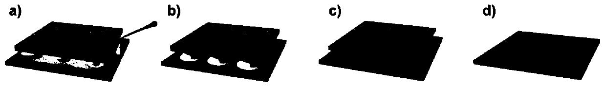
[0033] A method for preparing a perovskite microring resonator array, by adding perovskite MAPbBr 3 The precursor solution is confined between the template and the substrate, and the evaporation of the solvent is promoted by heating, so that the solution shrinks to the junction of the template micro-column structure and the substrate, forming a ring of high-concentration precursor solution around the micro-column. When the concentration reaches a After a certain value, crystallization begins around the micro-column to form a ring-shaped crystal, and the micro-ring resonator array conforming to the structure of the template is obtained after the template is removed.

[0034] A perovskite microring resonator array, the specific steps are as follows:

[0035] (1), the preparation of the template;

[0036] The specific steps are as follows: use photolithography to prepare the master template: firstly, a silicon wafer with a size of 25×25 mm and a thickness of 1 mm is ultrasonicat...

Embodiment 2

[0049] Based on MAPbBr 3 Microring resonators are used in laser resonators.

[0050] A perovskite microring resonator array has the characteristics of designable size and shape, simple preparation process and short time consumption, and has the advantage of complete shape, and can be used as a resonator in laser equipment. Since the obtained MAPbBr 3 Microrings are crystals that have very good light-emitting properties and thus act as a gain medium as well as a resonator. Under the action of a certain pump light, the microring resonator confines light of different specific wavelengths in the ring and amplifies the output to realize laser emission.

[0051] A perovskite microring resonator array is used as a microring resonator laser, and the specific steps are as follows:

[0052] Steps (1), (2), (3) are the same as in Example 1.

[0053] (4), preparation of microring resonator laser: MAPbBr obtained through steps (1), (2), (3) 3 Microring resonator arrays are directly us...


PUM

PropertyMeasurementUnit
diameteraaaaaaaaaa
heightaaaaaaaaaa
thicknessaaaaaaaaaa

Abstract

The invention discloses a perovskite micro-ring resonator array, a preparation method and application thereof. The invention belongs to the technical field of perovskite crystal patterning. The preparation method comprises: limiting an organic-inorganic hybrid perovskite MAPbBr<3> precursor solution in the middle of a template with a microstructure; and the perovskite crystal is nucleated and crystallized along the edge of the microstructure of the protruding part on the template through heating, the template is removed after crystallization is completed, and finally the MAPbBr<3> micro-ring resonator array is prepared. According to the main principle, the crystallization process is controlled at the edge of a micro-column by utilizing the induction effect of the edge of a micro-column structure protruding out of a template on crystallization, and finally the micro-ring resonator array with the shape consistent with the shape and size of the structure of the template micro-column arrayis obtained.

Description

technical field [0001] The invention belongs to the technical field of perovskite crystal patterning, and in particular relates to a perovskite microring resonator array, a preparation method and an application thereof. Background technique [0002] In recent years, the development of optoelectronic information technology requires the integration of optoelectronic devices to be higher and higher. Therefore, due to its compact structure, high integration and rich functions, microring resonators are widely used as the basic construction of photonic integrated systems. one of the elements. Although in other material systems, the preparation process of microrings is very mature and simple, in the perovskite material system, due to its inherent crystallization tendency, microring resonators are difficult to realize. At present, the main preparation method of perovskite microring resonators is to control the crystal shape through polystyrene spheres. However, this method faces d...

Claims


Application Information

Patent Timeline
Patent Type & Authority Applications(China)
IPC IPC(8): H01S5/10G02B6/12G02B6/13C30B29/60C30B29/12C30B7/06
CPCC30B7/06C30B29/12C30B29/60G02B6/12004G02B6/12007G02B6/13H01S5/1082
Inventor 孙洪波李顺心夏虹
Owner JILIN UNIV
Learn More