Refuse landfill membrane concentration leachate treatment method

A landfill and treatment method technology, applied in the field of landfill membrane concentration leachate treatment, can solve the problems such as the difficulty of pollutant-enriched sewage treatment, and achieve disposal problems, harmless treatment, and simple operation Effect

Inactive Publication Date: 2020-07-03
武汉天源环保股份有限公司
View PDF3 Cites 3 Cited by
  • Summary
  • Abstract
  • Description
  • Claims
  • Application Information

AI Technical Summary

Problems solved by technology

[0004] The purpose of the present invention is to overcome the difficulty of sewage treatment caused by conti

Method used


Image

  • Refuse landfill membrane concentration leachate treatment method

Examples


Example Embodiment

[0037] Example 1:

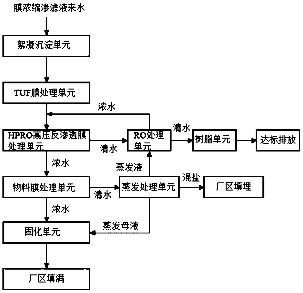
[0038] A waste landfill in Shandong has 83,000 cubic meters of membrane-concentrated leachate in stock. The COD of the membrane concentrate is 6000mg / L, the ammonia nitrogen is 1500mg / L, the total nitrogen is 2200mg / L, and the conductivity is 55000uS / cm. The current design is 300t / d treatment system. use as figure 1 As shown in the process flow chart, firstly, 0.1% calcium oxide, 0.2% PAC and 0.001% PAM are added to the flocculation sedimentation unit, and after 3 hours of reaction and precipitation, it enters the TUF membrane treatment unit. At this stage, the COD removal rate reaches 20%, ammonia nitrogen The removal rate reaches 10%, the total nitrogen removal rate reaches 15%, and the conductivity removal rate reaches 5%. The water produced by the TUF membrane treatment unit enters the HPRO high-pressure reverse osmosis membrane treatment unit. Its operating pressure is 120bar, the water production rate reaches 70%, the COD removal rate of the produce...

Example Embodiment

[0040] Example 2:

[0041] A waste landfill in Jiangsu produces 100 tons of membrane-concentrated leachate per day. The COD of the membrane concentrate is 3280mg / L, the ammonia nitrogen is 1200mg / L, and the conductivity is 3640uS / cm. A 100t / d treatment system is now designed. use as figure 1 As shown in the process flow chart, firstly, 0.05% calcium oxide, 0.15% PAC and 0.002% PAM are added to the flocculation sedimentation unit, and after 2 hours of reaction and precipitation, it enters the TUF membrane treatment unit. At this stage, the COD removal rate reaches 15%, ammonia nitrogen The removal rate reaches 10%, the total nitrogen removal rate reaches 15%, and the conductivity removal rate reaches 5%. The water produced by the TUF membrane treatment unit enters the HPRO high-pressure reverse osmosis membrane treatment unit. Its operating pressure is 110bar, the water production rate reaches 75%, the COD removal rate of the produced water reaches 85%, the ammonia nitrogen re...


PUM

PropertyMeasurementUnit
Conductivityaaaaaaaaaa

Abstract

The invention provides a refuse landfill membrane concentration leachate treatment method. The method comprises the following steps: firstly, refuse landfill membrane concentration leachate sequentially enters a flocculation precipitation unit, a TUF membrane treatment unit and an HPRO high-pressure reverse osmosis membrane treatment unit, clear water generated by the HPRO high-pressure reverse osmosis membrane treatment unit is introduced into an RO treatment unit, clear water generated after treatment of the RO treatment unit enters a resin unit, and generated concentrated water is introduced into the HPRO high-pressure reverse osmosis membrane treatment unit again and is treated; and concentrated water generated by the HPRO high-pressure reverse osmosis membrane treatment unit is introduced into a material membrane treatment unit, clear water treated by the material membrane treatment unit is introduced into the evaporation treatment unit and is evaporated, and the concentrated water of the material membrane treatment unit and evaporation mother liquor are introduced into the solidification unit and are solidified. The problems of high sewage treatment difficulty caused by continuous recharging of the existing membrane concentrated leachate and continuous enrichment of pollutants and serious bubbles and scaling of an evaporation system are solved, and reduction and harmlesstreatment of the landfill leachate are realized.

Description

technical field [0001] The invention belongs to the technical field of waste water treatment, and in particular relates to a method for treating landfill membrane concentrated leachate. Background technique [0002] Landfill leachate is the sewage seeped out due to fermentation and precipitation scour, surface water and groundwater soaking during garbage stacking and landfilling. At present, the commonly used treatment method is biochemical method + membrane method. However, in areas where the carbon-to-nitrogen ratio is seriously out of balance or the temperature in the north is low, it is difficult to control the wastewater biochemical system. Faced with this dilemma, high-pressure reverse osmosis membranes were born and have sprung up in applications all over the country. High-pressure reverse osmosis membranes have an important Small ground, high degree of automation, movable integrated processing, short installation and commissioning cycle. However, this kind of proce...

Claims


Application Information

Patent Timeline
IPC IPC(8): C02F9/10C02F103/06
CPCC02F1/001C02F1/04C02F1/285C02F1/441C02F1/444C02F1/5236C02F1/56C02F9/00C02F2103/06C02F2303/14
Inventor 黄开明高本修冷超群李红王雪霞胡文立陈俊
Owner 武汉天源环保股份有限公司
Why Eureka
Try Eureka