Semi-solid molding equipment and process for non-ferrous metal particles

A semi-solid forming, non-ferrous metal technology, used in metal processing equipment, equipment for supplying molten metal, casting equipment, etc., can solve problems such as difficulty in forming large billets, restricting application scope, etc., achieving good compactness, saving manufacturing costs, The effect of a short turnaround time

Active Publication Date: 2021-10-29
刘兴军
View PDF9 Cites 0 Cited by
  • Summary
  • Abstract
  • Description
  • Claims
  • Application Information

AI Technical Summary

Problems solved by technology

[0005] The invention provides a semi-solid forming equipment for non-ferrous metal particles such as aluminum, magnesium and zinc, which breaks through the bottleneck of the existing metal semi-solid forming equipment, that is, solves the problem that the existing forming equipment can only form small specifications, light weight, and thick walls. Parts products with less drop, it is difficult to form super large, super thick and heavy large parts and prefabricate various large blanks, and solve the existing horizontal and vertical semi-solid forming equipment for aluminum, magnesium and zinc metals, using axial feeding , molten material, high-pressure and high-speed unidirectional injection molding process, which greatly restricts the application scope of existing aluminum, magnesium, and zinc metal semi-solid equipment.

Method used


Image

  • Semi-solid molding equipment and process for non-ferrous metal particles
  • Semi-solid molding equipment and process for non-ferrous metal particles
  • Semi-solid molding equipment and process for non-ferrous metal particles

Examples


Embodiment 1

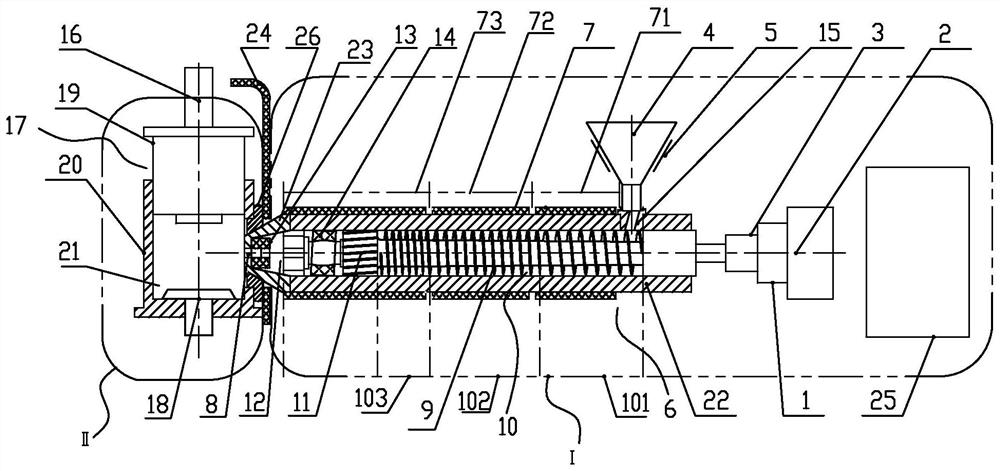
[0039] exist figure 1 , figure 2 In the illustrated embodiment, a semi-solid molding device for non-ferrous metal particles includes:

[0040] One-section horizontal feeding mechanism I, one-section horizontal feeding mechanism is used to realize the conveying, melting, mixing, storage, and feeding of metal particles into the molding cavity; one-section horizontal feeding mechanism includes quantitative control system 1 , feed pressure system 2, feed rotation system 3, material storage device 4, drying system 5, barrel device 6 and segmental gradient heating system 7;

[0041] Two-section vertical forming mechanism II, the two-section vertical forming mechanism is used to realize die forging and die-casting;

[0042] The working direction of the horizontal feeding mechanism of the first section is vertical to the working direction of the vertical forming mechanism of the second section, and the horizontal feeding mechanism of the first section is connected with the vertical...


PUM


Abstract

The invention discloses a non-ferrous metal granule semi-solid forming equipment, comprising: a section horizontal feeding mechanism, the said one section horizontal feeding mechanism is used to realize metal particle transportation, melting, mixing, storage, into the molding cavity; the one-section horizontal feeding mechanism is equipped with: a barrel device arranged horizontally, a segmental gradient heating system set outside the barrel device, and a shear opening structure with the barrel device The docked material storage device and the drying system arranged outside the material storage device; the two-section vertical forming mechanism, the two-section vertical forming mechanism is used to realize die forging and die-casting; the one-section horizontal feeding mechanism The working direction of the two-section vertical forming mechanism is perpendicular to that of the two-section vertical forming mechanism, and the first-section horizontal feeding mechanism is internally connected with the second-section vertical forming mechanism, and the horizontal feeding is realized through a smooth-type discharge port. , vertically shaped. Also disclosed is a non-ferrous metal particle semi-solid molding process.

Description

technical field [0001] The invention relates to the technical field of non-ferrous metal particles semi-solid forming process and equipment, in particular to a non-ferrous metal particle semi-solid forming process and equipment. Background technique [0002] The existing aluminum-magnesium-zinc non-ferrous metal particle semi-solid die-casting molding equipment is the most novel and cutting-edge metal material molding process equipment after the liquid metal die-casting molding process equipment. The semi-solid forming process equipment die-casts various thin-walled parts with excellent quality In liquid die-casting, good compactness. All aspects of mechanical properties are better than liquid metal die-casting parts. For example, the tensile strength of the aluminum-magnesium-zinc alloy is significantly increased by more than 20-25% after semi-solid forming. But at present domestic and foreign vertical or bedroom semi-solid die-casting molding equipment all adopt axial mo...

Claims


Application Information

Patent Timeline
Patent Type & Authority Patents(China)
IPC IPC(8): B22D18/02B22D39/00B22D1/00
CPCB22D1/007B22D18/02B22D39/00
Inventor 刘兴军刘绍东
Owner 刘兴军
Why Eureka
Try Eureka