
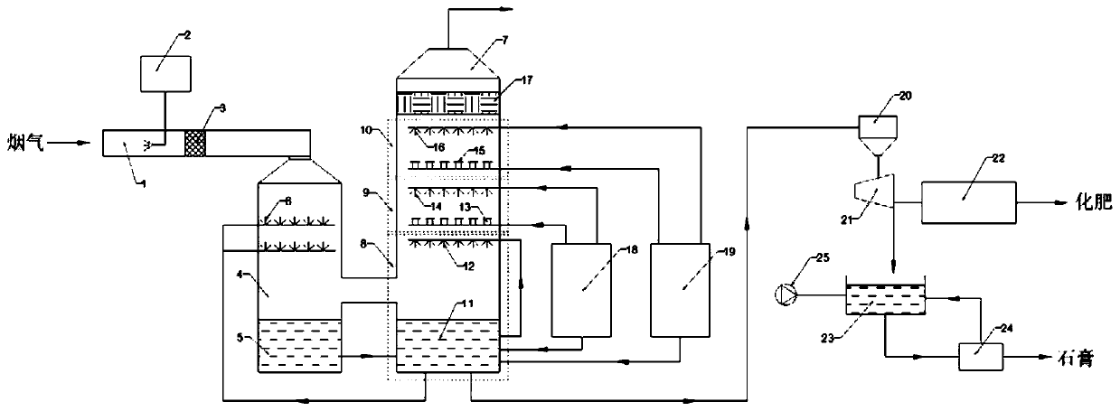
Desulfurization and denitrification system and method by adopting ozone oxidation in cooperation with ammonia method

A desulfurization, denitrification and ozone oxidation technology, which is applied in the field of desulfurization and denitrification systems of ozone oxidation and ammonia method, can solve the problems of ammonia escape, waste of energy consumption, high investment and operating costs, and achieves enhanced oxidation efficiency, reduced equipment corrosion, and alleviated whitening. effect of smoke

Pending Publication Date: 2020-08-07
GUANGDONG J TECH ENVIRONMENT SCI CO LTD
View PDF3 Cites 3 Cited by
  • Summary
  • Abstract
  • Description
  • Claims
  • Application Information

AI Technical Summary

Problems solved by technology

[0006] However, there are still some problems in ammonia desulfurization at present: the circulating fluid contains 2 Ammonium sulfite with absorption function also contains a large amount of ammonium sulfate, which causes a large amount of energy consumption and waste of circulating liquid pump power; ammonia absorbent consumes a lot and has the problem of ammonia escape; the outlet flue gas is easy to carry small droplets and aerosol, it is difficult to remove completely; the quality of the by-product ammonium sulfate is not high, the overall equipment investment and operating costs are relatively high, etc.
[0011] When there are sulfur dioxide and nitrogen oxides in the flue gas at the same time, there are a series of problems such as the mutual influence of the two processes, high energy consumption and operating costs, large floor area, and high equipment investment for the separate treatment of sulfur dioxide and nitrogen oxides.

Method used


Image

  • Desulfurization and denitrification system and method by adopting ozone oxidation in cooperation with ammonia method

Examples


Embodiment 1

[0091] This embodiment provides a desulfurization and denitrification method of ozone oxidation in cooperation with ammonia method, and the desulfurization and denitrification method specifically includes:

[0092] (1) The ozone generating device 2 feeds ozone into the inlet flue 1, and the flue gas passes into the inlet flue 1 and contacts with ozone countercurrently, and the mol ratio of the ozone passing into the inlet flue 1 to NO in the flue gas is 0.8, After mixed and fully oxidized by the mixing device 3, it is sent to the first absorption device 4; the first absorbent storage tank 18 and the second absorbent storage tank 19 respectively inject quicklime and ammonia water into the circulating spray pool 11 of the second absorption device 7, The mixed absorbent formed in the circulating spray tank 11 passes into the spray device 6 of the first absorption device 4, the pH of the mixed absorbent sprayed in the first absorption device 4 is controlled at 5.3, and the oxidized...

Embodiment 2

[0097] This embodiment provides a desulfurization and denitrification method of ozone oxidation in cooperation with ammonia method, and the desulfurization and denitrification method specifically includes:

[0098] (1) The ozone generating device 2 feeds ozone into the inlet flue 1, and the flue gas passes into the inlet flue 1 and contacts with the countercurrent flow of ozone, and the mol ratio of the ozone passing into the inlet flue 1 to NO in the flue gas is 0.9, After being fully oxidized by the mixing device 3, it is sent to the first absorption device 4; the first absorbent storage tank 18 and the second absorbent storage tank 19 respectively inject limestone and ammonia water into the circulating spray pool 11 of the second absorption device 7, The mixed absorbent formed in the circulating spray tank 11 is passed into the spray device 6 of the first absorption device 4, the pH of the mixed absorbent sprayed in the first absorption device 4 is controlled at 5.6, and the...

Embodiment 3

[0103] This embodiment provides a desulfurization and denitrification method of ozone oxidation in cooperation with ammonia method, and the desulfurization and denitrification method specifically includes:

[0104] (1) The ozone generating device 2 feeds ozone into the inlet flue 1, and the flue gas passes into the inlet flue 1 and contacts with ozone countercurrently, and the mol ratio of the ozone passing into the inlet flue 1 to NO in the flue gas is 1, After mixed and fully oxidized by the mixing device 3, it is sent to the first absorption device 4; the first absorbent storage tank 18 and the second absorbent storage tank 19 respectively inject steel slag and ammonia water into the circulating spray pool 11 of the second absorption device 7, The mixed absorbent formed in the circulating spray tank 11 is passed into the spray device 6 of the first absorption device 4, and the pH of the mixed absorbent sprayed in the first absorption device 4 is controlled at 6, and the oxid...


PUM


Abstract

The invention provides a desulfurization and denitrification system and method by adopting ozone oxidation in cooperation with an ammonia method. The desulfurization and denitrification system comprises a first absorption device and a second absorption device which are sequentially communicated in the flue gas flow direction. An ozone generation device is connected into an inlet flue of the firstabsorption device; the interior of the second absorption device is sequentially divided into a circulating spraying area and at least two layers of multi-effect spraying areas from bottom to top in the flue gas flowing direction, the circulating spraying area is externally connected with at least two absorbent storage tanks, the absorbent storage tanks are independently connected into the multi-effect spraying areas respectively, and the absorbent storage tanks supply absorbents to the circulating spraying area and the multi-effect spraying areas respectively; and the circulating spraying areais externally connected with a recovery unit. By adopting a double-tower structure for absorption, the retention time of the absorbent in the tower is prolonged, the contact time with flue gas is prolonged, and the desulfurization and denitrification efficiency is improved. A mixed absorbent of ammonia water and a calcium-based absorbent is adopted, and NOx in the flue gas is converted into chemical fertilizer and gypsum with higher additional value.

Description

technical field [0001] The invention belongs to the technical field of desulfurization and denitrification, and relates to a desulfurization and denitrification system and method, in particular to a desulfurization and denitrification system and method of ozone oxidation and ammonia method. Background technique [0002] In recent years, flue gas SO in my country's iron and steel, coking, metallurgy and other non-electric industries 2 , NO x The emission reduction has received widespread attention. National and local governments continue to introduce increasingly stringent emission standards, which puts the industry under enormous pressure to reduce emissions. Taking steel and coking industries as examples, sintering flue gas and coke oven flue gas are the main SO 2 and NO x Emission source. The emission temperature of these flue gases is generally low (150-250°C), which cannot meet the temperature window of the traditional SCR process. Therefore, the SCR denitrification...

Claims


Application Information

Patent Timeline
IPC IPC(8): B01D53/78B01D53/60B01D53/76B01D53/56C01C1/18C01C1/247C01C1/22C01F11/48C01F11/46
CPCB01D53/78B01D53/60B01D53/76B01D53/56C01C1/185C01C1/247C01C1/22C01F11/48C01F11/464B01D2258/0283B01D2251/104B01D2251/2062Y02A50/20
Inventor 刘勇胡小吐杨颖欣杨森林莫伟智邓小勇
Owner GUANGDONG J TECH ENVIRONMENT SCI CO LTD
Learn More