
Multi-channel acquisition and control integrated soil gas flux monitoring system and monitoring method

A soil gas and monitoring system technology, applied in soil material testing, temperature measurement of moving fluid, measuring devices, etc., can solve problems of unfavorable engineering practice, can not comprehensively consider the influence of soil respiration coupling, heavy weight and other problems

Pending Publication Date: 2020-08-07
阜新工大华联科技有限公司
View PDF1 Cites 4 Cited by
  • Summary
  • Abstract
  • Description
  • Claims
  • Application Information

AI Technical Summary

Problems solved by technology

[0003] Based on the published patent "An Intelligent Soil Gas Flux Monitoring Data Acquisition System" (the patent application number is CN201920807690.X, and the authorized publication (announcement) number is CN 210037800 U), there are the following problems: 1) The monitoring channel is single
For the assessment of soil GHG respiration, only CO 2 or O 2 As one of the gases, the coupling effect of soil respiration and surface vegetation photosynthesis cannot be considered comprehensively, which affects the credibility of the data; in the monitoring and early warning of coal spontaneous combustion in coal seams or goafs, the indicator gases include CO 2 , CO, CH 4 and sulfide, etc., multiple characteristic gases are collected at the same point synchronously and mutually verified to achieve accurate and reliable determination of the combustion state, fire zone range, moving direction, and moving speed. Reduce monitoring efficiency and assessment accuracy
2) Unreasonable structural design
The monitoring system adopts industrial control modules with high cost and large volume, which leads to the separate design of the control system and the acquisition system. There are disadvantages such as complicated wiring, large volume, heavy weight, large floor space, and difficult transportation. , sampling distance, and site conditions are relatively limited, and portability and field adaptability are relatively poor
3) The details of the air chamber are not perfect
The gas sensor unit is placed in the soil ring. During the manual installation and removal of the sensor, it will inevitably cause vibration to the precise electronic components in the gas sensor unit, shorten its working life, and affect the monitoring accuracy.
On the other hand, there is no rain-proof facility outside the air exchange port of the gas chamber, and the probability of water immersion in the gas sensor unit in the gas chamber increases in rainy and snowy weather, which greatly reduces the service life of the sensor
4) Function settings are not flexible
The client cannot set and change monitoring parameters such as the number of monitoring cycles, monitoring time, and sampling interval at will. If necessary, parameter changes can only be realized through program debugging with an external computer, which cannot meet the requirements of different experiments and is not conducive to solving different projects. practice problem
5) The system operation is not intelligent
There is no visual interface, and the system running status and data collection cannot be grasped in real time, and the files can only be viewed by manually exporting files to the PC through USB media
On the other hand, wireless remote control cannot be realized, and special personnel are required to be responsible for on-the-spot observation of system operation status and file transfer management, and it is difficult to improve monitoring efficiency

Method used


Image

  • Multi-channel acquisition and control integrated soil gas flux monitoring system and monitoring method
  • Multi-channel acquisition and control integrated soil gas flux monitoring system and monitoring method
  • Multi-channel acquisition and control integrated soil gas flux monitoring system and monitoring method

Examples


Embodiment Construction

[0054] The invention will be further described below in conjunction with the accompanying drawings and specific implementation examples. The following preferred embodiments are only exemplary, and the present invention includes but is not limited to the following embodiments.

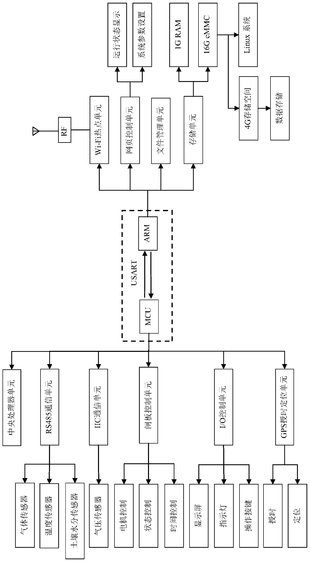
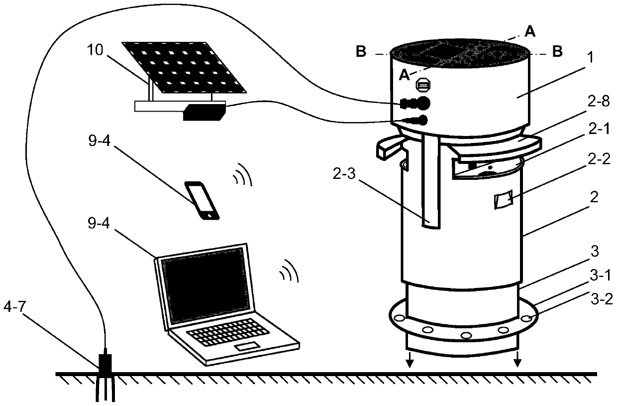
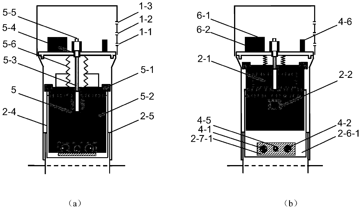
[0055] Such as Figure 1-2 As shown, a multi-channel acquisition and control integrated soil gas flux monitoring system includes a controller 1, a sensor unit, a gas chamber unit, and a human-computer interface 9;

[0056] Described controller 1 comprises MCU single-chip microcomputer 6-1 and ARM application processor 6-2, and MCU single-chip microcomputer 6-1 carries out data interaction with ARM application processor 6-2 by USART mode;

[0057] The sensor unit includes a gas sensor unit, a temperature sensor 4-5, an air pressure sensor 4-6 and a soil moisture sensor 4-7, and the gas sensor unit includes but is not limited to CO 2 Sensor 4-1, O 2 Sensor 4-2, CO sensor 4-3, CH 4 Sensors 4-4, each senso...


PUM


Abstract

The invention provides a multi-channel acquisition and control integrated soil gas flux monitoring system and a monitoring method. The system comprises a controller, a sensor unit, an air chamber unitand a human-computer interaction interface. An MCU, an ARM application processor and a Linux operating system are adopted in the controller. High integration of system control and data acquisition isrealized, visual man-machine interaction interface, GPS time service positioning, Wi-Fi wireless communication and PC / mobile phone webpage end remote control are supported, and arbitrary addition andcombination of CO2 / O2 / CO / CH4 and other gas sensors are supported. The user side supports the functions of monitoring parameter setting, real-time data display, file transmission management and the like. The system is based on the in-situ monitoring concept, the problem of air barrier and the problem of air pressure imbalance in an air chamber are avoided, and the influence of external force suchas an air pump on the air release rate is eliminated. The system can be widely applied to long-term continuous monitoring and scientific research experiments of soil gas flux in a complex environmentunder the field unattended condition.

Description

technical field [0001] The invention relates to the technical field of gas flux monitoring in the fields of ecology, environmental protection, mining, and safety, and in particular to a multi-channel mining and control integrated soil gas flux monitoring system and monitoring method. Background technique [0002] Soil is the most important core component of the terrestrial ecosystem. It is not only the producer of the earth, it maintains water and nutrients to maintain plant growth, and supplies terrestrial organisms through the food chain; Decompose into carbon dioxide or inorganic nitrogen, inorganic phosphorus and other small molecules, and then enter the material cycle again. While regulating plant growth and material circulation, the soil is constantly exchanging gases with the atmosphere (CO 2 , nitrogen oxides, sulfides, etc.), maintaining the stability of the composition of the atmosphere. Therefore, the long-term continuous monitoring of surface soil gas flux is o...

Claims


Application Information

Patent Timeline
IPC IPC(8): G01N33/24G01K13/02G01K13/024
CPCG01N33/24G01N33/246G01K13/02G01K13/024
Inventor 赵明春佐佐木久郎张晓明王永军张河猛王琢杨晓晨董伟刘筱颖李婉静
Owner 阜新工大华联科技有限公司
Learn More