Supercharge Your Innovation With Domain-Expert AI Agents!

Array substrate, manufacturing method thereof, display panel and display device

A technology of an array substrate and a manufacturing method, which is applied in the display field, can solve problems such as failure of an insulating layer, poor swelling of electrodes and insulating layers, and poor adhesion, and achieve the effects of improving adhesion, avoiding poor short circuits, and preventing swelling

Pending Publication Date: 2020-08-18
BOE TECH GRP CO LTD +1
View PDF4 Cites 6 Cited by
  • Summary
  • Abstract
  • Description
  • Claims
  • Application Information

AI Technical Summary

Problems solved by technology

[0003] However, there are also some difficulties in the production process of oxide semiconductor displays. IGZO, as the material of the active layer, is very sensitive to hydrogen and water. The insulating material must use silicon oxide (SiOx) material with relatively strong water resistance, but the SiOx film The stress generally manifests as a large negative stress (about -350Mpa), while the Cu thin film as an electrode material generally exhibits a positive stress (about 300Mpa). It can be seen that there is a large stress difference between the electrode and the insulating layer, and the electrode and the insulating layer The layers are mainly connected by van der Waals force, and the adhesion is poor. In actual production, there are often bad bulges between the electrodes and the insulating layer; The high temperature will cause Cu to grow into the insulating layer to form copper whiskers and break down the insulating layer, causing the insulating layer to fail, resulting in a short circuit (Short), which seriously affects the product yield.

Method used


Image

  • Array substrate, manufacturing method thereof, display panel and display device
  • Array substrate, manufacturing method thereof, display panel and display device
  • Array substrate, manufacturing method thereof, display panel and display device

Examples


Embodiment Construction

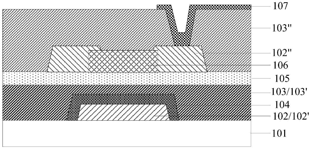
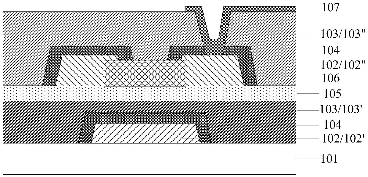
[0033] In order to make the purpose, technical solutions and advantages of the embodiments of the present invention more clear, the following will clearly and completely describe the technical solutions of the embodiments of the present invention in conjunction with the drawings of the embodiments of the present invention. The thickness and shape of each film layer in the drawings do not reflect the real scale, and the purpose is only to illustrate the content of the present invention. Apparently, the described embodiments are some, not all, embodiments of the present invention. Based on the described embodiments of the present invention, all other embodiments obtained by persons of ordinary skill in the art without creative efforts shall fall within the protection scope of the present invention.

[0034] Unless otherwise defined, the technical terms or scientific terms used herein shall have the usual meanings understood by those skilled in the art to which the present invent...


PUM


Abstract

The invention discloses an array substrate, a manufacturing method of the array substrate, a display panel and a display device. The array substrate comprises an underlayer substrate, a conductive layer, a silicon-based intermediate layer and an insulating layer, wherein the conductive layer, the silicon-based intermediate layer and the insulating layer are sequentially located on the underlayer substrate, and the silicon-based intermediate layer is fixedly connected with the conductive layer and the insulating layer through chemical bonds. The silicon-based intermediate layer fixedly connected with the conductive layer (such as an electrode) and the insulating layer through the chemical bonds is arranged between the conductive layer and the insulating layer, so that the adhesive force between the conductive layer and the insulating layer is effectively improved, the conductive layer and the insulating layer are prevented from bulging due to poor adhesion under the internal stress of afilm layer. In addition, atoms (such as copper atoms) in the conductive layer can be effectively pinned by the chemical bonds between the silicon-based intermediate layer and the conductive layer, and poor short circuit between the conductive layer (such as a gate metal layer) and a subsequent conductive layer (such as a source-drain metal layer) caused by diffusion growth of the conductive layerto the insulating layer in a high-temperature environment in the manufacturing process is avoided. Therefore, the product yield is improved.

Description

technical field [0001] The present invention relates to the field of display technology, in particular to an array substrate, a manufacturing method thereof, a display panel, and a display device. Background technique [0002] Existing flat panel display devices mainly include Liquid Crystal Display (Liquid Crystal Display, LCD) devices and Organic Light Emitting Display (Organic Light Emitting Display, OLED) devices. Due to the inherent defect of low electron mobility, thin-film transistors with amorphous silicon (a-Si) as the active layer are increasingly unable to meet people's demands for high-end products such as high resolution, high refresh rate, and full screen. Demand, oxide semiconductors (such as indium gallium zinc oxide, Indium Gallium Zinc Oxide, IGZO) have high electron mobility (about 10 times that of a-Si), good switching ratio, and compared with low temperature polysilicon (Low Temperature Polysilicon) Silicon, LTPS) has a simple process and low cost, and ...

Claims


Application Information

Patent Timeline
IPC IPC(8): H01L27/12H01L21/77
CPCH01L27/1248H01L27/1262H01L27/1225H01L29/66969H01L29/4908H01L29/7869H01L29/401
Inventor 汪涛黄寅虎高锦成钱海蛟张瑞锋朱登攀
Owner BOE TECH GRP CO LTD
Features
  • R&D
  • Intellectual Property
  • Life Sciences
  • Materials
  • Tech Scout
  • Unparalleled Data Quality
  • Higher Quality Content
  • 60% Fewer Hallucinations
Learn More