Perovskite solar cell and preparation method thereof
A solar cell and perovskite technology, applied in the field of solar energy, can solve the problems of improvement, low electron mobility of the electron transport layer, affecting cell efficiency, etc., and achieve the effects of simple preparation process, enhanced electron transport capability, and improved production efficiency.
- Summary
- Abstract
- Description
- Claims
- Application Information
AI Technical Summary
Problems solved by technology
Method used
Image
Examples
Embodiment 1
[0021] figure 1 Schematic diagram of the structure of the perovskite solar cell provided in Example 1 of the present application. Such as figure 1 As shown, the perovskite solar cell includes a conductive glass layer, an electron transport layer, a perovskite layer, a hole transport layer and a metal electrode layer arranged sequentially from bottom to top. Wherein, the above-mentioned conductive glass layer is used to collect electrons in the electron transport layer. The electron transport layer is used to transport electrons from the perovskite layer to the conductive glass layer. The above perovskite layer is used to absorb sunlight energy and is excited to form hole-electron pairs; the above hole transport layer is used to transport the holes generated by the perovskite layer. From the hole to the metal electrode layer, the metal electrode layer is used to receive the holes transported from the hole transport layer and recombine with the electrons from the conductive gl...
Embodiment 2
[0023] figure 2 Schematic diagram of the structure of the perovskite solar cell provided in Example 2 of the present application. Such as figure 2 As shown, compared with the structure of the perovskite solar cell provided in Example 1, the perovskite solar cell provided in this embodiment can also include an interface modification layer, and the above interface modification layer is arranged between the electron transport layer and the perovskite layer Between, the material of the interface modification layer can be barium hydroxide. By adding a layer of Ba(OH) between the electron transport layer and the perovskite layer 2 The interface modification layer, on the one hand, can improve the charge collection efficiency, reduce the carrier recombination center, increase the number of carriers, and improve the photoelectric performance; on the other hand, it can also optimize the crystal quality of the perovskite layer and the film interface, so that The density of pores an...
Embodiment 3
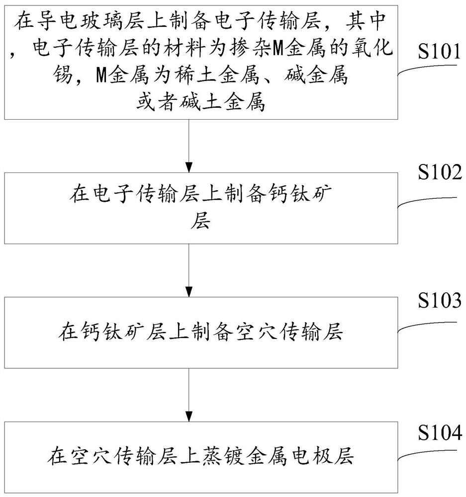
[0025] The following description is as follows figure 1 The fabrication method of the perovskite solar cell with the structure shown. image 3 It is a schematic diagram of the preparation method of the perovskite solar cell provided in Example 3 of the present application. Such as image 3 As shown, the method includes: step S101: preparing an electron transport layer on the conductive glass layer; wherein, the material of the electron transport layer is tin oxide doped with M metal, and the M metal is a rare earth metal, an alkali metal or an alkaline earth Metal. Step S102: preparing a perovskite layer on the electron transport layer; step S103: preparing a hole transport layer on the perovskite layer; step S104: evaporating a metal electrode layer on the hole transport layer. The specific content of the above steps will not be repeated here, and reference may be made to the specific content of the steps in Embodiment 4 below.
PUM
 Abstract
Description
Claims
Application Information
 - R&D
- Intellectual Property
- Life Sciences
- Materials
- Tech Scout
- Unparalleled Data Quality
- Higher Quality Content
- 60% Fewer Hallucinations
Browse by: Latest US Patents, China's latest patents, Technical Efficacy Thesaurus, Application Domain, Technology Topic, Popular Technical Reports.
© 2025 PatSnap. All rights reserved.Legal|Privacy policy|Modern Slavery Act Transparency Statement|Sitemap|About US| Contact US: help@patsnap.com


