An Unsteady State Oil and Gas Recovery System

An oil and gas recovery system and unsteady state technology, which is applied in the recovery of liquid hydrocarbon mixtures, the petroleum industry, and the treatment of hydrocarbon oil, etc., can solve problems such as oil and gas freezing, affecting the normal operation of heat exchangers, etc., to ensure safety and eliminate explosion risks Effect

Active Publication Date: 2022-04-15
上海同济华康环境科技有限公司 +1
View PDF9 Cites 0 Cited by
  • Summary
  • Abstract
  • Description
  • Claims
  • Application Information

AI Technical Summary

Problems solved by technology

The disadvantage is that because the flow of oil and gas changes greatly, the load can be reduced from 100% to 0 in a short time. For the exhaust gas containing high boiling point components, such as water vapor and some macromolecular organic substances, once the flow suddenly drops, the flow of liquid nitrogen will be reduced. If the adjustment is not timely, the excessive liquid nitrogen and the huge temperature difference between the cold and hot fluids will freeze the oil and gas in the precooler, forming ice blockages, which will affect the normal operation of the heat exchanger

Method used


Image

  • An Unsteady State Oil and Gas Recovery System
  • An Unsteady State Oil and Gas Recovery System
  • An Unsteady State Oil and Gas Recovery System

Examples


Embodiment 1

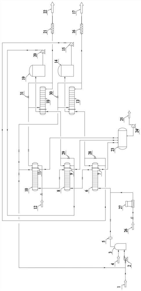
[0042] Provide an unsteady state oil and gas recovery system, including air intake system, safety system, primary condensing system, secondary condensing system, cryogenic heat exchange system, primary ethylene glycol cooling system, secondary ethylene glycol cooling system, Ethylene glycol storage and delivery system, low temperature oil and gas heating system, low temperature nitrogen heating system, liquid nitrogen delivery and adjustment system, condensate recovery and delivery system and defrosting system;

[0043] The air intake system includes an oil and gas input pipeline 1 and a fan 2 connected in sequence, the safety system includes a nitrogen dilution pipeline 4, a buffer tank 3 and an oxygen concentration analyzer 5 connected in sequence, and the primary condensing system includes a sequentially connected A primary condensation heat exchanger 6 and a primary gas-liquid separator 7, the secondary condensation system includes a secondary condensation heat exchanger 8 ...

Embodiment 2

[0059] Such as figure 1 As shown, the system flow of this embodiment is the same as that of Embodiment 1.

[0060] The oil and gas in this embodiment comes from the tail gas of a C4 oil product tank farm loading in a petrochemical plant, and the oil and gas treatment capacity is 500m 3 / h, after testing, the total non-methane hydrocarbon content in oil and gas is about 50g / m 3 , and contains a certain amount of water vapor. After the oil gas 1 is collected, it is sent to the buffer tank 3 through the fan 2. Since the oxygen content in oil gas 1 is about 21%, there is a risk of explosion, so nitrogen needs to be added for dilution. Nitrogen 4 is also sent to the buffer tank 3, and the oil gas and nitrogen gas are fully mixed in the buffer tank and then discharged. Use the oxygen concentration analyzer 5 to measure the oxygen content in the mixed oil and gas, and control the flow rate of dilute nitrogen to ensure that the oxygen content is lower than 8 %, the amount of dilut...


PUM


Abstract

The invention relates to an unsteady-state oil and gas recovery system, including an air intake system, a safety system, a primary condensation system, a secondary condensation system, a cryogenic heat exchange system, a primary glycol cooling system, and a secondary glycol cooling system. system, ethylene glycol storage and delivery system, low temperature oil and gas heating system, low temperature nitrogen heating system, liquid nitrogen delivery and adjustment system, condensate recovery and delivery system and defrosting system. The primary condensing system and the secondary condensing system of the present invention use low-temperature ethylene glycol-water solution as the refrigerant instead of gaseous medium as the refrigerant, so that the condensation temperature of the oil and gas can be controlled more accurately, and the high boiling point components in the oil and gas can be condensed into The liquid phase flows into the condensate storage tank without excessive condensation to form frost, which will cause the heat exchanger to freeze and affect the stable operation of the entire system.

Description

technical field [0001] The invention relates to the technical field of oil and gas recovery, in particular to an unsteady oil and gas recovery system. Background technique [0002] Oil storage tanks in petrochemical plants, refineries, and chemical plants will discharge high-concentration oil and gas from the breathing valve on the top of the tank when oil enters the tank or the ambient temperature rises. When oil products are loaded into cars, trains or ships, oil and gas with a high concentration will also be discharged from the top of the car and ship. The concentration of these oils and gases is relatively high, usually between 10 and 1000g / m 3 Between, and the concentration and flow fluctuate greatly, if these oil vapors are distributed in the atmosphere, it will not only pollute the air, but also a waste of oil products. [0003] For the treatment of such high-concentration, non-steady-state oil and gas, one of the more commonly used methods is liquid nitrogen conden...

Claims


Application Information

Patent Timeline
Patent Type & Authority Patents(China)
IPC IPC(8): C10G5/06B65D90/30B67D7/04
CPCC10G5/06B65D90/30B67D7/049C10G2300/4006C10G2300/4081
Inventor 赵修华胡雪沁王其南
Owner 上海同济华康环境科技有限公司
Why Eureka
Try Eureka