Laser-welded compressor shell body and welding method thereof

A compressor shell and laser welding technology, which is applied to laser welding equipment, welding equipment, mechanical equipment, etc., can solve the problems of welding slag around the welding surface of the shell, limited production capacity, and high cost, so as to improve the appearance quality of the product and reliability, the welding joint is small and uniform, and the effect of eliminating burrs

Pending Publication Date: 2020-09-22
WUHU ABAUR MECHANICAL & ELECTRICAL
View PDF0 Cites 0 Cited by
  • Summary
  • Abstract
  • Description
  • Claims
  • Application Information

AI Technical Summary

Problems solved by technology

[0002] At present, shell welding is the bottleneck of the entire compressor production process, and the welding efficiency is low, resulting in limited production capacity
At the same time, the consumables in the welding process are relatively large. For example, welding wire is required for each compressor welding. During the welding process, welding leakage often occurs, which leads to slag in the welding of the compressor, water ingress during the water inspection, and some even lead to the entire compressor. machine scrap
Due to the use of welding wire in the welding process, welding slag often appears around the welding surface of the shell, which seriously affects the appearance of the compressor. Therefore, it is necessary to add a brushing and slag removal process after the ring welding, which is time-consuming, laborious and expensive.
[0003] In the prior art, laser welding has not been able to be applied to the welding technology of the compressor shell due to the limitation of structural shape and process

Method used


Image

  • Laser-welded compressor shell body and welding method thereof
  • Laser-welded compressor shell body and welding method thereof
  • Laser-welded compressor shell body and welding method thereof

Examples


Embodiment 1

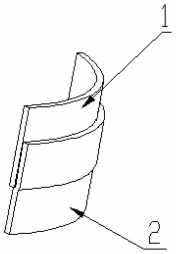
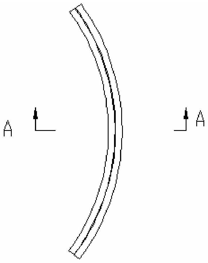
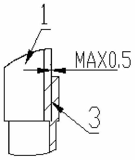
[0058] Such as Figure 1 to Figure 4 and Figure 9 Shown: a laser welded compressor casing, the shape of the upper cover 1 and the lower casing 2 is oval on the cross-section where the upper cover 1 and the lower casing 2 are connected; mouth fit; the maximum clearance of the said seam fit is 0.5mm.

[0059] The weld pool 3 formed by the upper cover 1 and the lower shell 2 has a maximum penetration depth of 1.8mm, and a maximum fusion height 4 of 1.2mm.

[0060] The height of the seam fit is 8.5-9.5 mm. The stop structure is adopted to ensure the accuracy of the position during the welding process.

[0061] The upper cover 1 forms a weld seam 3 through the matching gap formed with the lower casing 2. When the welding seam 3 formed by the matching gap formed between the upper cover 1 and the lower casing 2 is at most 0.5mm, the laser gun head 7 is pumped with the optical fiber and The focused high-energy laser spot formed by conduction will cooperate with the melting of the...

Embodiment 2

[0068] Such as Figure 5 , Figure 6 and Figure 9 Shown: a laser-welded compressor shell, including a lower shell 2 and an upper cover 1 matched with it, the shape of the connecting section of the upper cover 1 and the lower shell 2 is elliptical; The upper cover 1 and the lower case 2 adopt a spigot fit; the maximum gap of the spigot fit is 0.4 mm; the lower case 2 is provided with a maximum depth on the edge of the upper cover 1 Chamfering of the seam of the lower shell not exceeding 1.2mm and width not exceeding 0.15mm5.

[0069] The weld pool 3 formed by the upper cover 1 and the lower shell 2 has a maximum penetration depth of 2.1mm, and a maximum fusion height 4 of 1.5mm.

[0070] The height of the seam fit is 8.5-9.5mm. The stop structure is adopted to ensure the accuracy of the position during the welding process.

[0071] The upper cover 1 forms a welding seam 3 through the matching gap formed with the lower casing 2. When the maximum depth of the lower casing 2...

Embodiment 3

[0078] Such as Figure 7 , Figure 8 and Figure 9 Shown: a laser-welded compressor shell, including a lower shell 2 and an upper cover 1 matched with it, the shape of the connecting section of the upper cover 1 and the lower shell 2 is elliptical; The upper cover 1 and the lower case 2 adopt a spigot fit; the maximum gap of the spigot fit is 0.4 mm; the lower case 2 is provided with a maximum depth on the edge of the upper cover 1 R arc 6 of the seam of the lower shell not exceeding 1.4mm and width not exceeding 0.15mm.

[0079] The weld pool 3 formed by the upper cover 1 and the lower shell 2 has a maximum penetration depth of 2.3mm, and a maximum fusion height 4 of 1.6mm.

[0080] The height of the seam fit is 8.5-9.5mm. The stop structure is adopted to ensure the accuracy of the position during the welding process.

[0081] The upper cover 1 forms a weld 3 through the matching gap formed with the lower casing 2. When the maximum depth of the lower casing 2 does not ex...


PUM

PropertyMeasurementUnit
heightaaaaaaaaaa
diameteraaaaaaaaaa
Defocus amountaaaaaaaaaa

Abstract

The invention discloses a laser-welded compressor shell body. The laser-welded compressor shell body comprises a lower shell body (2) and an upper cover (1) matched with the lower shell body, and theshape of the connection section of the upper cover (1) and the lower shell body (2) is elliptical; the upper cover (1) and the lower shell body (2) are matched by a spigot; and the maximum clearance of the spigot matching is 0.5 mm. The invention further discloses a laser welding method of the compressor shell body. According to the technical scheme, the continuous laser welding is achieved, the welding efficiency is high, and the welding strength is higher than base metal cold rolled steel or hot rolled steel; the welding joint strength is high; the appearance is neat and beautiful; and fiberlaser welding is based on the fusion of a self shell plate to for a molten pool connection, a welding wire is eliminated, the thermal deformation area is small, thus the damage of laser heat conduction to a pump body enclosed in the shell body is greatly reduced, the product cost is lowered, and the appearance quality and reliability of the product are improved.

Description

technical field [0001] The invention relates to a refrigeration compressor and its manufacturing technology, in particular to the welding structure and laser welding method of the upper and lower shells of the compressor. Background technique [0002] At present, shell welding is the bottleneck of the entire compressor production process, and the welding efficiency is low, resulting in limited production capacity. At the same time, the consumables in the welding process are relatively large. For example, welding wire is required for each compressor welding. During the welding process, welding leakage often occurs, resulting in slag in the welding of the compressor, water ingress during the water inspection, and some even lead to the entire compressor. The machine is scrapped. Due to the use of welding wire in the welding process, welding slag often appears around the welding surface of the shell, which seriously affects the appearance of the compressor. Therefore, a brushin...

Claims


Application Information

Patent Timeline
Patent Type & Authority Applications(China)
IPC IPC(8): B23K26/046B23K26/21B23K26/70F04B39/12
CPCB23K26/046B23K26/21B23K26/702F04B39/121
Inventor 何景云戴勇军王世林王昱张小利尚亮亮穆丹陈超超汤超
Owner WUHU ABAUR MECHANICAL & ELECTRICAL
Why Eureka
Try Eureka