Supercharge Your Innovation With Domain-Expert AI Agents!

Ion neutralizer based on cold cathode

A cold cathode and cathode technology, applied in the direction of using plasma, machine/engine, thrust reverser, etc., can solve the problems of complex structure, long warm-up time, cost increase, etc., achieve simple overall structure, reduce overall weight, The effect of reducing complexity

Active Publication Date: 2020-10-02
UNIV OF ELECTRONIC SCI & TECH OF CHINA
View PDF15 Cites 0 Cited by
  • Summary
  • Abstract
  • Description
  • Claims
  • Application Information

AI Technical Summary

Problems solved by technology

[0003]Hot cathode has a high status in previous research, development and application. At this stage, hot cathode technology is very mature and is widely used in various electric vacuum devices, but with the continuous in-depth research on cold cathodes, the advantages of cold cathodes in various aspects are gradually highlighted; first, the structure is simple: hot cathodes usually require a high temperature in practical applications, so the thermal emission structure , material heat resistance and other aspects have higher requirements, which increases the cost and complicates the structure; second, the efficiency is high: due to the heating of the hot cathode and the loss of heat energy, the overall efficiency of the system is greatly reduced; Three, long life: the working environment of the hot cathode will inevitably affect the life of each component; Fourth, the system is stable: the hot cathode is prone to short circuit, open circuit and other problems in a high temperature environment, making it difficult for the device to work normally; Five, start faster: For hot cathodes, it often takes a long time to warm up to reach the working temperature

Method used


Image

  • Ion neutralizer based on cold cathode
  • Ion neutralizer based on cold cathode
  • Ion neutralizer based on cold cathode

Examples


Embodiment Construction

[0028] Below in conjunction with the accompanying drawings, the specific embodiments of the present invention will be further described; in order to better illustrate the embodiments, there will be omissions, enlargement or reduction in the drawings.

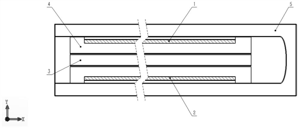
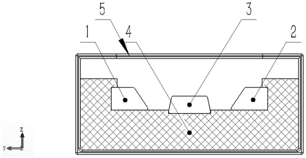
[0029] This embodiment provides a kind of ion neutralizer based on cold cathode, its structure is as follows figure 1 , figure 2 shown; It should be noted that the following X, Y, Z directions are as follows figure 1 and figure 2 As shown, that is, the standard Cartesian coordinate system conforming to the right-hand rule, and figure 1 The single hatched surface in the middle represents the cold cathode emitting surface, figure 2 The cross-hatched surface represents the media support layer.

[0030] The above-mentioned ion neutralizer based on cold cathode includes: left cathode 1, right cathode 2, center anode 3, dielectric support layer 4 and anode casing 5; The base of the anode 3 is used to fix the assembly, that is,...


PUM


Abstract

The invention belongs to the field of vacuum electronics, and particularly provides an ion neutralizer based on a cold cathode. The ion neutralizer based on the cold cathode is used for neutralizing surplus positive ions in an ion propeller. The ion neutralizer based on the cold cathode comprises a left cathode 1, a right cathode 2, a central anode 3, a medium supporting layer 4 and an anode outershell 5; the left cathode and the right cathode are symmetrically arranged relative to the central anode, and the left cathode, the right cathode and the central anode are all arranged on the mediumsupporting layer, the anode outer shell wraps the medium supporting layer, a U-shaped hole is formed in the top face of the anode outer shell, and nano cold cathode emission surfaces are arranged on the inclined side edges of the left cathode and the right cathode. According to the ion neutralizer based on the cold cathode, the cold cathode is used as an emission source, so that the complexity, energy consumption, volume and weight of the device are reduced to a great extent; meanwhile, through the structural design and voltage adjustment, complete emission of a electron beam is guaranteed, and bunching of an external magnetic field is not needed; in conclusion, the ion neutralizer is simple in structure and low in energy consumption, and it can be guaranteed that electrons generated by the cathodes are completely emitted out through the opening of the anode outer shell and fully neutralized with positive ion flow.

Description

technical field [0001] The invention belongs to the field of vacuum electronics, and in particular relates to an ion neutralizer based on a cold cathode, which is mainly used for neutralizing excess positive ions in an ion thruster. Background technique [0002] Ion thrusters are a new generation of aerospace propulsion power devices. Compared with traditional chemical propulsion methods, ion thrusters not only have a large specific impulse, but also simplify the overall structure of spacecraft. The ion thruster accelerates the positive ions and ejects them outward through the grid to generate thrust. Because it continuously ejects the positive ion beam, a large number of negative ions remain in the injection tube, and the electric field force makes the positive ions unable to continue to go out smoothly. Therefore, a corresponding neutralization device must be installed outside the propulsion port of the ion injector, so that the propeller can continuously obtain thrust. T...

Claims


Application Information

Patent Timeline
IPC IPC(8): F03H1/00
CPCF03H1/0025
Inventor 袁学松崔仲韬鄢扬李海龙王彬殷勇蒙林
Owner UNIV OF ELECTRONIC SCI & TECH OF CHINA
Features
  • R&D
  • Intellectual Property
  • Life Sciences
  • Materials
  • Tech Scout
  • Unparalleled Data Quality
  • Higher Quality Content
  • 60% Fewer Hallucinations
Learn More