Fuel gas decoupling combustor and using method thereof

A burner, gas technology, applied in the combustion method, gas fuel burner, burner and other directions, can solve the problems of reducing the local air volume, reducing the combustion temperature, unfavorable combustion efficiency, etc., to expand the mixing position area, reduce the temperature peak , the effect of expanding the stable combustion range

Active Publication Date: 2020-10-16
INST OF PROCESS ENG CHINESE ACAD OF SCI
View PDF10 Cites 2 Cited by
  • Summary
  • Abstract
  • Description
  • Claims
  • Application Information

AI Technical Summary

Problems solved by technology

Due to the small flow rate and high temperature of the flue gas internal circulation, it is necessary to make full use of the heat dissipation capacity of the combustion chamber and require a high flow rate of the combustion gas, which further increases the energy consumption of the fan. Therefore, specific combustion methods and furnace types are often used. ; When external circulation of flue gas with low flue temperature is adopted, the combustion temperature and thermal NO can be significantly reduced by increasing the circulating air volume X generation, but the combustion stability and combustion efficiency decrease, the flow rate of the fan and the system resistance increase, and the energy consumption increases
[0005] In the prior art, there are also technical solutions that simultaneously adopt staged diffusion combustion or a small amount of premixing. This type of technical solution mainly uses fuel segmented mixed combustion, and the fuel injection ports are arranged in groups and intervals on the outer circumference of the combustion-supporting air, and the circumference is relatively long. The annular air flow can reduce the local air volume, increase the air-fuel mixing time and the length of the diffusion combustion flame, but the main combustion area of ​​the diffusion combustion method is small, and the high-temperature area is concentrated, which reduces the radiation heat dissipation and convective heat transfer of the flue gas; Part of the gas leaves the airflow in the main combustion zone at the front end, which can control the local thermal intensity of the diffusion combustion in the middle and front stages, but it will cause a large amount of unstable low-temperature combustible gas to accumulate, increase combustion fluctuations, and cause a large risk of deflagration. Safety at low load and ignition stages reduce
[0006] In addition, in order to control and prolong the air-fuel mixture and increase the entrainment capacity, the main air flow of the above-mentioned technical solution mostly adopts a straight-line injection with the nozzle shrinking inward, and the fullness of the combustion chamber flame is reduced, which is not good for heat dissipation and stable combustion.
In addition, in order to reduce the central temperature of the flame, the amount of fuel arranged in the central combustion area is very small, which is not conducive to the stable combustion of the flame, but also causes the relative concentration of the peripheral fuel, which strengthens the way of diffusion combustion, which is not conducive to reducing the heat Type NO X generation
[0007] For measures such as fuel segmental mixed combustion and flue gas internal circulation, such technical solutions weaken the combustion at the front of the combustion chamber, reduce the radiation heat dissipation of the flue gas, concentrate the high temperature area of ​​the combustion chamber to the rear, and the average flue gas temperature is still high ; Moreover, the fullness of the flue gas in the combustion chamber is low, the smoke velocity in the main combustion zone increases, and the residence time of combustibles is short, which is not conducive to ensuring the combustion efficiency after staged combustion

Method used


Image

  • Fuel gas decoupling combustor and using method thereof
  • Fuel gas decoupling combustor and using method thereof

Examples


Embodiment 1

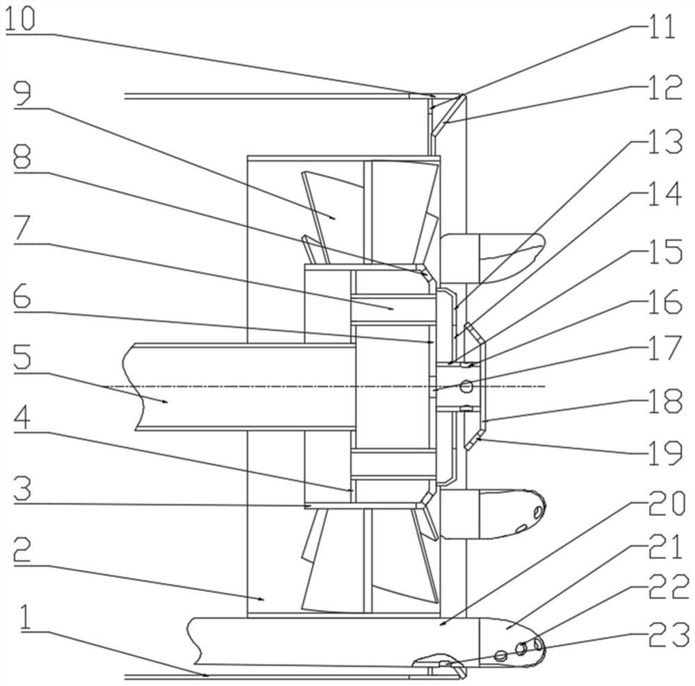
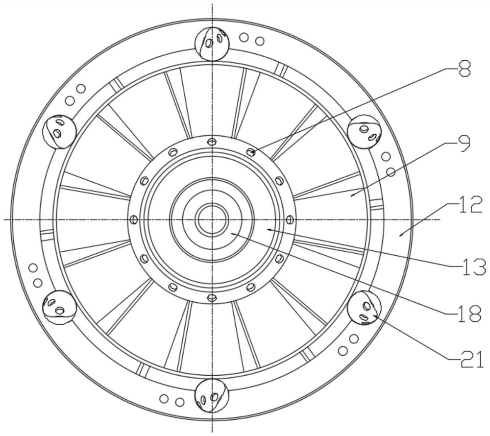
[0108] This embodiment provides a gas decoupling burner. The gas decoupling burner includes a central gas assembly, a cylinder body 2 and an outer cylinder body 1 arranged coaxially from the inside to the outside; the central gas assembly and An annular main air passage is formed between the cylinders 2 ; an annular outer air passage is formed between the cylinders 2 and the outer cylinder 1 .

[0109] The central gas assembly includes a central cylinder 3, a central gas chamber rear cover 4 and a central gas chamber front panel 6; the central cylinder 3, the central gas chamber rear cover 4 and the central gas chamber front panel 6 form a central In the gas chamber, the central axis of the cylinder body 3 coincides with that of the cylinder body 2, the front panel 6 of the central gas chamber is on the side close to the combustion chamber, and the rear cover plate 4 of the central gas chamber is on the side away from the combustion chamber.

[0110] The rear cover plate 4 of ...

Embodiment 2

[0119] This embodiment provides a gas decoupling burner. The gas decoupling burner includes a central gas assembly, a cylinder body 2 and an outer cylinder body 1 arranged coaxially from the inside to the outside; the central gas assembly and An annular main air passage is formed between the cylinders 2 ; an annular outer air passage is formed between the cylinders 2 and the outer cylinder 1 .

[0120]The central gas assembly includes a central cylinder 3, a central gas chamber rear cover 4 and a central gas chamber front panel 6; the central cylinder 3, the central gas chamber rear cover 4 and the central gas chamber front panel 6 form a central In the gas chamber, the central axis of the cylinder body 3 coincides with that of the cylinder body 2, the front panel 6 of the central gas chamber is on the side close to the combustion chamber, and the rear cover plate 4 of the central gas chamber is on the side away from the combustion chamber.

[0121] The rear cover plate 4 of t...

Embodiment 3

[0131] This embodiment provides a gas decoupling burner. The gas decoupling burner includes a central gas assembly, a cylinder body 2 and an outer cylinder body 1 arranged coaxially from the inside to the outside; the central gas assembly and An annular main air passage is formed between the cylinders 2 ; an annular outer air passage is formed between the cylinders 2 and the outer cylinder 1 .

[0132] The central gas assembly includes a central cylinder 3, a central gas chamber rear cover 4 and a central gas chamber front panel 6; the central cylinder 3, the central gas chamber rear cover 4 and the central gas chamber front panel 6 form a central In the gas chamber, the central axis of the cylinder body 3 coincides with that of the cylinder body 2, the front panel 6 of the central gas chamber is on the side close to the combustion chamber, and the rear cover plate 4 of the central gas chamber is on the side away from the combustion chamber.

[0133] The rear cover plate 4 of ...


PUM


Abstract

The invention relates to a fuel gas decoupling combustor and a using method thereof. The fuel gas decoupling combustor adopts a partition staged combustion mode of central and peripheral oxygen deficit and central area lean combustion, diffusion type oxygen-deficient combustion with high combustion stabilizing capacity and low heat intensity is adopted in the central combustion area, reliable ignition and low-load stable combustion of the oxygen-deficient combustion area are ensured, the peripheral oxygen-deficient combustion area controls temperature distribution of a combustion chamber by accurately controlling partition mixing of fuel gas and air, the radiation heat transfer capacity is improved, and mixed burnout of the peripheral fuel gas and the main combustion area is promoted. In aword, the problem that the combustion temperature of a diffusion combustion mode is too high in the central stage is effectively solved by the fuel gas decoupling combustor and the using method thereof, the combustion chamber is more uniform in heat intensity, high in flame fullness, high in heat transfer capacity and long in smoke retention time, the combustion efficiency is guaranteed under thecondition of low fan power consumption, meanwhile, generation of thermal NOX is reduced, and decoupling combustion of the fuel gas is achieved.

Description

technical field [0001] The invention belongs to the technical field of combustion, and relates to a burner, in particular to a gas decoupling burner and a use method thereof. Background technique [0002] High calorific value gas has the characteristics of rapid combustion and high theoretical combustion temperature, but it is easy to generate thermal NO in the combustion process. X , for the traditional diffusion combustion method, due to the poor uniformity of air-fuel mixing and combustion, it is easy to cause a wide distribution of flame high-temperature areas and a high peak temperature of flame combustion. X Very unfavorable. [0003] Premixed combustion can significantly improve the uniformity of combustion, but the combustion stability and safety are reduced. Surface combustion technology is the most widely used fully premixed combustion method at present. Through dense hole network and narrowing the outlet aperture of the mixed gas to the limit tempering However, ...

Claims


Application Information

Patent Timeline
Patent Type & Authority Applications(China)
IPC IPC(8): F23D14/08F23D14/26F23D14/46F23D14/70F23D14/64F23D14/58
CPCF23D14/08F23D14/26F23D14/46F23D14/58F23D14/64F23D14/70F23D2203/007F23D2900/14003F23D2900/14241
Inventor 郝江平高士秋余剑李剑玲赵康
Owner INST OF PROCESS ENG CHINESE ACAD OF SCI
Why Eureka
Try Eureka