
Method for forming cantilever beam probe based on femtosecond laser and high temperature and cantilever beam probe

A cantilever beam probe, femtosecond laser technology, applied in scanning probe technology, scanning probe microscopy, processes for producing decorative surface effects, etc., can solve complex manufacturing processes, low molding efficiency, and experimental equipment. expensive, etc.

Pending Publication Date: 2020-10-27
HANGZHOU DIANZI UNIV
View PDF13 Cites 2 Cited by
  • Summary
  • Abstract
  • Description
  • Claims
  • Application Information

AI Technical Summary

Problems solved by technology

The above-mentioned technologies have a series of shortcomings such as expensive experimental equipment, extremely complicated manufacturing process and low molding efficiency.
The defects in the existing technology have inhibited the application and development of the micro-cantilever beam in the field of sensors to a certain extent
It can be seen that the production method uses techniques such as chemical etching and sputtering, so expensive test equipment is still required, and the manufacturing process is also extremely complicated.

Method used


Image

  • Method for forming cantilever beam probe based on femtosecond laser and high temperature and cantilever beam probe
  • Method for forming cantilever beam probe based on femtosecond laser and high temperature and cantilever beam probe
  • Method for forming cantilever beam probe based on femtosecond laser and high temperature and cantilever beam probe

Examples


Embodiment 1

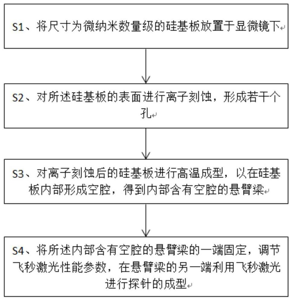
[0035] refer to figure 1 , 2 , 3, 4, 5 This embodiment provides a method based on femtosecond laser and high temperature forming cantilever beam probe, including steps:

[0036] S1. Place the silicon substrate 1 with a size on the order of micro-nanometers under a microscope;

[0037] S2. Perform ion etching on the surface of the silicon substrate 1 to form several holes 2;

[0038] S2. Perform high-temperature molding on the silicon substrate 1 after ion etching to form a cavity 3 inside the silicon substrate 1 to obtain a cantilever beam 6 containing the cavity 3 inside;

[0039] S4. Fix one end of the cantilever beam 6 containing the cavity 3 inside, adjust the performance parameters of the femtosecond laser 4, and use the femtosecond laser 4 to shape the probe at the other end of the cantilever beam 6.

[0040] The micro-cantilever beam probe is the most important part of the micro-sensor, and it is generally prepared by low-pressure chemical vapor deposition, chemical ...

Embodiment 2

[0046] refer to Figure 5 , the present invention also provides a cantilever beam probe 8, using the preparation method as described in Embodiment 1, the cantilever beam 6 of the cantilever beam probe 8 contains a cavity 3, thus improving the resonance of the cantilever beam probe 8 frequency, so that the detection accuracy of the cantilever beam probe 8 becomes higher.

[0047] refer to Figure 6 , the working principle of the cantilever beam probe 8 of the present invention is: the laser emitter 9 emits laser light to the cantilever beam probe 8, and the laser light is irradiated to the photodetector 10 after reflection, because when the cantilever beam probe 8 contacts the object 11 , the probe 7 will produce a slight deformation, so the deflection of the cantilever beam 6 will also be slightly deformed. At this time, the light beam irradiated to the photodetector 10 by reflection produces an offset, so that the cantilever beam 6 can be deduced Elastic deformation Δx, and f...


PUM


Abstract

The invention belongs to the field of micro-nano manufacturing, and particularly relates to a method for forming a cantilever beam probe based on femtosecond laser and high temperature and the cantilever beam probe. The forming method comprises the following steps: S1, placing the silicon substrate with the micro-nano order of magnitude under a microscope; S2, performing ion etching on the surfaceof the silicon substrate to form a plurality of holes; S3, performing high-temperature forming on the silicon substrate after ion etching to form a cavity in the silicon substrate to obtain a cantilever beam with the cavity inside; and S4, fixing one end of the cantilever beam internally provided with the cavity, adjusting femtosecond laser performance parameters, and forming the probe at the other end of the cantilever beam by using femtosecond laser. The method for manufacturing the cantilever beam probe is simple and effective, the cost required for purchasing expensive test equipment is saved, and the cavity is formed in the cantilever beam, so that the resonant frequency of the cantilever beam probe is improved, and the detection precision of the cantilever beam probe is improved.

Description

technical field [0001] The invention belongs to the field of micro-nano manufacturing, and in particular relates to a method for forming a cantilever beam probe based on femtosecond laser and high temperature and the cantilever beam probe. Background technique [0002] Microcantilever is an extremely precise micromechanical structure, which is widely used in the field of microsensors and atomic force microscopes. Its working principle is to convert extremely small physical signal changes and chemical signal changes into electrical signal changes, which is convenient for accurate calculation and recording in the later stage. Common physical signal changes and chemical signal changes are mainly surface pressure changes, thermal changes, and chemical reaction changes of the cantilever beam. [0003] The micro-cantilever probe is the most important part of the micro-sensor, and it is generally prepared by low-pressure chemical vapor deposition, chemical corrosion, and sputterin...

Claims


Application Information

Patent Timeline
Patent Type & Authority Applications(China)
IPC IPC(8): B81C1/00G01Q60/38
CPCB81C1/00111B81C1/0015B81C1/00547B81C1/00047G01Q60/38
Inventor 刘红英刘光献顾春川邓敏樊凯李杜娟厉力华陈建龙
Owner HANGZHOU DIANZI UNIV
Learn More