Silicon-based millimeter wave receiving front-end circuit

A receiving front-end, millimeter wave technology, applied in electrical components, modulation and transformation balancing devices, modulation transfer, etc., can solve the problems of increasing the hardware overhead of the oscillator circuit, doubling the power consumption, and large signal loss of the local oscillator.

Pending Publication Date: 2020-10-30
CHENGDU UNIV OF INFORMATION TECH
View PDF2 Cites 9 Cited by
  • Summary
  • Abstract
  • Description
  • Claims
  • Application Information

AI Technical Summary

Problems solved by technology

[0004] Millimeter wave phased array receiver system applied to intermediate frequency phase shifting structure, such as figure 1 As shown in (b), an existing mmWave wideband receiver front-end (Chun-Hsing Li, Chien-Nan Kuo, and Ming-Ching Kuo, “A 1.2-V 5.2-mW20–30-GHz Wideband Receiver Front-End in 0.18-μm CMOS,” IEEETrans.Microw.Theory Tech., vol.60, no.11, pp.3502–3512, 2012.), using baluns to achieve wideband signal output, and also realized low-noise amplifier to mix The single-ended to differential output of the frequency converter, but it needs two mixers of I and Q channels, and a phase

Method used


Image

  • Silicon-based millimeter wave receiving front-end circuit
  • Silicon-based millimeter wave receiving front-end circuit
  • Silicon-based millimeter wave receiving front-end circuit

Examples


Embodiment Construction

[0028] For the convenience of those skilled in the art to understand the technical contents of the present invention, below in conjunction with the attached Figure 1-8 The content of the present invention is further explained.

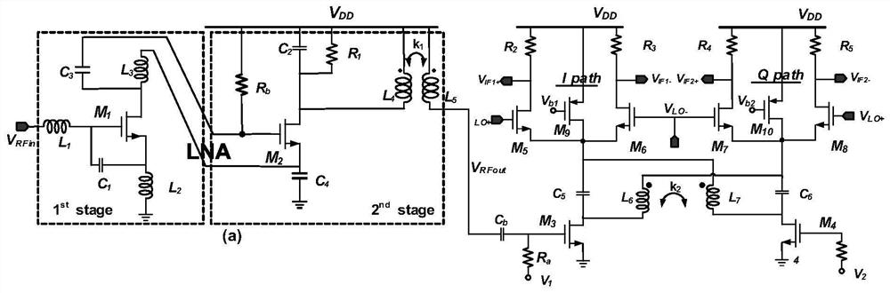
[0029] Such as figure 2 Shown is a silicon-based millimeter-wave receiving front-end circuit diagram proposed by the present invention. The technical solution of the present invention is: a millimeter-wave receiving front-end, including: a cascode low-noise amplifier, a transconductance input stage, and an orthogonal coupling stage , switching mixer stage and output load stage. Among them, the cascode low noise amplifier receives the radio frequency voltage signal, amplifies the radio frequency voltage signal, and inputs it to the transconductance input stage; the transconductance input stage converts the radio frequency voltage signal into a radio frequency current signal, and then inputs it to the quadrature coupling stage; The cross-coupling sta...


PUM


Abstract

The invention discloses a silicon-based millimeter wave receiving front-end circuit, which is applied to the field of radio frequency integrated circuits and is used for solving the problems of high power consumption, high cost and poor performance in the prior art. The silicon-based millimeter wave receiving front-end circuit comprises a cascode low-noise amplifier, a transconductance input stage, a quadrature coupling stage, a switch frequency mixing stage and an output load stage. The orthogonal coupling stage is designed at the mixer part, so that two paths of output signals at the receiving front end are equal in size, the phase difference is 90 degrees, the linearity is improved, and two paths of output are realized by using the same mixer, thereby reducing the power consumption.

Description

technical field [0001] The invention belongs to the field of radio frequency integrated circuits, in particular to a receiving front-end circuit. Background technique [0002] The mmWave frequency band will be used for future high-speed wireless services and communication applications. In recent years, potential wireless applications in the Ka-band (26.5-40GHz) include wireless point-to-multipoint services, satellite communications, radiolocation and imaging systems, etc. These systems require low cost, small size, higher levels of system integration and high performance RF, mmWave components such as low noise amplifier and mixer unit modules. [0003] The receiving front-end is very important in the entire receiving system. It mainly includes low-noise amplifiers and mixers, which can filter the signals we need from the received signals to facilitate subsequent processing and application of the receiver. The millimeter-wave receiving front-end will continue to develop in ...

Claims


Application Information

Patent Timeline
IPC IPC(8): H03D7/14
CPCH03D7/1441
Inventor 郭本青王雪冰刘海峰
Owner CHENGDU UNIV OF INFORMATION TECH
Why Eureka
Try Eureka