Two-stage groove type distributing device provided with pressure stabilizing plate and used for thin-layer drying equipment

A thin-layer drying and pressure-stabilizing plate technology, which is used in water distribution pipes, chemical instruments and methods, water/sludge/sewage treatment, etc. problems, to achieve high overall distribution uniformity, avoid temperature unevenness, and achieve the effect of resource utilization

Pending Publication Date: 2020-12-04
江苏固环环境科技有限公司
View PDF0 Cites 3 Cited by
  • Summary
  • Abstract
  • Description
  • Claims
  • Application Information

AI Technical Summary

Problems solved by technology

In the process of multiple evaporation cycles, the organic matter and salt in the evaporated liquid will continue to accumulate, resulting in an increasingly high concentration of wastewater entering the evaporation crystallizer, resulting in a decrease in the effect of evaporation and crystallization, and an increase in the viscosity of the evaporated liquid. The larger the boiling point is, the higher the boiling point will be. On the other hand, when the content of organic matter is too high, it will cause foaming of the feed liquid during the evaporation and concentration process, which will affect the normal operation of conventional evaporation and crystallization equipment, and eventually lead to the paralysis of the entire evaporation system.
[0005] Second, the evaporating equipment is blocked
[0008] Under ideal conditions, the conventional spray liquid distributor can spray the mother liquor into droplets or cover the outer surface, and the droplets and droplets will be combined and accumulated to form a continuous and uniform liquid film for heat treatment with the main equipment of thin layer drying. Exchange; but in fact, it is difficult to control the pressure and flow rate during the spraying process, and it is impossible to determine whether the mother liquid is evenly arranged on the outer surface of the main equipment, and the mother liquid is easy to carry small droplets after evaporation and gasification, resulting in serious suction liquid Problem; In addition, for conventional spray liquid distributors, when the organic content of the mother liquor added to the liquid distributor is high, it is easy to form a viscous colloid, so that it accumulates in the groove between the main equipment, The liquid distribution is uneven during use, and as the running time continues to prolong, the mother liquid accumulated in the groove becomes more and more viscous, which makes the drying dryer unable to continue to operate; and for the lower submerged distributor, there is also a high The mother liquid containing organic matter evaporates continuously under the action of high heat, the concentration of organic matter continues to increase, and the fluidity of the mother liquid becomes worse and worse, making the equipment unable to operate
[0009] It can be seen that the structure of the liquid distributor directly affects the distribution of organic waste liquid and the quality of film formation in thin-layer drying equipment. The uniformity of the liquid film of high-salt organic waste liquid directly affects the heat transfer efficiency, thereby affecting the quality of high-salt organic waste liquid resources. Therefore, a reasonable and scientific liquid distributor is needed to realize the resource utilization of high-salt organic waste liquid

Method used


Image

  • Two-stage groove type distributing device provided with pressure stabilizing plate and used for thin-layer drying equipment
  • Two-stage groove type distributing device provided with pressure stabilizing plate and used for thin-layer drying equipment
  • Two-stage groove type distributing device provided with pressure stabilizing plate and used for thin-layer drying equipment

Examples


Embodiment

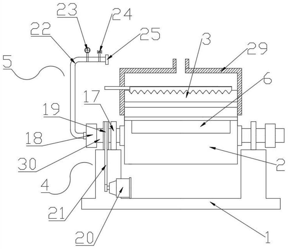
[0040] Embodiment: the present invention provides technical scheme, as figure 1 , a two-stage trough distributor with a pressure stabilizing plate for thin-layer drying equipment, including a support frame 1, a drying rotary column 2 is arranged on the upper end of the support frame 1, and the drying rotary column 2 is a rotating horizontal column structure, and the internal communication Heat conduction oil is used as the carrier when the mother liquor is dried, and it can evenly spread the mother liquor on its outer surface in cooperation with the secondary material distribution mechanism 3. The upper end of the drying rotary column 2 is provided with a secondary material distribution mechanism 3, which is used to The mother liquor is laid on the outer surface of the drying rotary column 2. On the one hand, it slows down the falling kinetic energy of the mother liquor and prevents the secondary material distribution mechanism 3 from being directly impacted by the mother liqu...


PUM


Abstract

The invention discloses a two-stage groove type distributing device provided with a pressure stabilizing plate and used for thin-layer drying equipment. A two-stage distributing mechanism comprises arectangular overflow groove, a U-shaped main groove, a flow stabilizing plate, a liquid conveying header pipe and liquid conveying pipes; the rectangular overflow groove is formed in the upper end ofa drying rotary column; the U-shaped main groove is formed in the upper end of the rectangular overflow groove; the flow stabilizing plate is arranged in the U-shaped main groove; a liquid conveying header pipe is arranged on one side of the U-shaped main groove; the plurality of liquid conveying pipes are arranged between the liquid conveying header pipe and the U-shaped main groove; and one endof each liquid conveying pipe penetrates into the U-shaped main groove; According to the two-stage distributing mechanism, on one hand, mother liquor descending kinetic energy is relieved, so that thetwo-stage d distributing mechanism is prevented from being directly impacted by large-flow mother liquor; on the other hand, feed liquid splashing caused by sharp fluctuation of the liquid level is avoided, the distribution uniformity of the mother liquor is effectively improved; and a complete, uniform and stable liquid film can be rapidly formed on the outer surface of a drying rotary column under the action of the gravity and surface tension of the mother liquor and the centrifugal force of the drying rotary column.

Description

technical field [0001] The invention relates to the field of dry drying evaporation concentration technology, in particular to a two-stage trough distributor with a pressure stabilizing plate for thin-layer drying equipment. Background technique [0002] High-salt and high-concentration organic waste liquid generally refers to waste liquid with COD>10,000mg / L and salt content>20,000mg / L, which mainly comes from fine chemical industries such as pesticides, pharmaceuticals, and coal chemical industry, and is refractory, highly toxic, and polluting high-level features. Complete separation of organic matter and salt in high-salt organic waste liquid is the key to realize the resource utilization and disposal of this kind of waste liquid. In order to completely separate organic matter and salt in waste liquid, conditions must first be created to crystallize the salt. [0003] At present, the conventional evaporation, concentration and crystallization technologies are mainl...

Claims


Application Information

Patent Timeline
Patent Type & Authority Applications(China)
IPC IPC(8): C02F1/08B01D9/02
CPCB01D9/0031C02F1/006C02F1/043C02F1/08
Inventor 朱化军朱成于平平于飞芹
Owner 江苏固环环境科技有限公司
Why Eureka
Try Eureka