High-temperature-resistant turbine generator rotor for space thermoelectric conversion and assembling method of high-temperature-resistant turbine generator rotor

A turbine generator and thermoelectric conversion technology, which is applied in gas turbine devices, engine components, machines/engines, etc., can solve the problems of deterioration of dynamic performance, increased operation risk, complex shaft structure, etc., and achieves optimization of dynamic characteristics, The effect of reducing complex processes and simplifying support structures

Active Publication Date: 2020-12-08
BEIJING INST OF CONTROL ENG
View PDF9 Cites 1 Cited by
  • Summary
  • Abstract
  • Description
  • Claims
  • Application Information

AI Technical Summary

Problems solved by technology

The rotor arranged in the traditional micro gas turbine for power generation is a split structure, which is composed of a separate turbine compressor rotor and a generator rotor connected in series. Although this structure uses the permanent magnet of the generator as an independent rotor placed in a normal temperature environment, As a result, the shafting structure is complicated, the dynamic performance is deteriorated, and the operation risk is increased.

Method used


Image

  • High-temperature-resistant turbine generator rotor for space thermoelectric conversion and assembling method of high-temperature-resistant turbine generator rotor
  • High-temperature-resistant turbine generator rotor for space thermoelectric conversion and assembling method of high-temperature-resistant turbine generator rotor
  • High-temperature-resistant turbine generator rotor for space thermoelectric conversion and assembling method of high-temperature-resistant turbine generator rotor

Examples


specific Embodiment

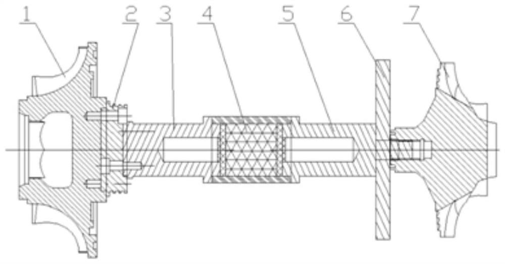
[0041] The structure of a specific embodiment of the invention is as follows: the typical value of the total length of the rotor is 338mm, and the shortest is not less than 300mm; the maximum diameter is located at the outer diameter of the turbine 1, the outer diameter of the turbine 1 is 148mm-160mm, and the length is 55mm-60mm; ceramic heat insulation Section 2 is 18mm-30mm in length and 62mm-70mm in diameter; the typical length of permanent magnet 4 is 176mm and 47mm in diameter; the high-temperature side connecting section 3 and the low-temperature side connecting section 5 are both 37mm in outer diameter and 60mm in length, and are semi-hollow structures. A blind hole with an inner diameter of 17 mm and a depth of 38 mm is opened at the section facing the permanent magnet 4; the thickness of the thrust plate 6 is 10 mm, and the outer diameter is 127 mm; the outer diameter of the compressor impeller 7 is 120 mm to 130 mm, and the axial length is 70 mm to 80 mm .

[0042] ...


PUM


Abstract

The invention discloses a high-temperature-resistant turbine generator rotor for space thermoelectric conversion and an assembling method of the high-temperature-resistant turbine generator rotor, andbelongs to the technical field of space nuclear power sources. The rotor is supported by an air bearing, a turbine at one end of the rotor is blown by high-temperature and high-pressure helium-xenonmixed gas or pure argon working medium gas during working, a permanent magnet at the middle section of the rotor is driven to synchronously rotate to generate power, and meanwhile, a gas compressor impeller at the other end of the rotor is driven to boost the pressure of the working medium gas of a thermodynamic cycle system. The rotor is compact in structure; and the design of a high-performanceheat insulation section is adopted, so that the middle-section permanent magnet can be effectively prevented against demagnetization failure while the rotor works under the ultrahigh temperature gradient. Through repeated iterative design, the bearing support limitation, the thermosetting coupling effect, the thermal protection requirement, the high-speed rotation working condition and the machining process requirement of the rotor are comprehensively considered, and the closed-type thermal power generation system has the characteristics of being light in weight, high in strength, high-temperature-resistant, thermal-shock-resistant, excellent in dynamic characteristics and high in reliability, and is suitable for high-power-density closed-type thermal power generation systems.

Description

technical field [0001] The present invention relates to a turbine generator rotor for space thermoelectric conversion and an assembly method thereof, and various types of closed-type Brayton cycle power generation devices are applied, including space vehicle power, underwater submersible vehicle power, non-internal combustion thermal power conversion engines, etc. It belongs to the technical field of space nuclear power supply. [0002] technical background [0003] With the application of electric propulsion platforms for spacecraft and the needs of deep space exploration missions, my country has carried out research on various electric propulsion technologies and made great progress. Restricted by factors such as sunshine time and power level, it is difficult to meet the power requirements of deep space exploration. The closed-type Brayton cycle thermoelectric conversion technology plans to use nuclear reactors as heat sources, and is suitable for long-duration, non-sunshin...

Claims


Application Information

Patent Timeline
Patent Type & Authority Applications(China)
IPC IPC(8): F01D5/04F01D5/02F01D15/10F02C3/08
CPCF01D5/048F01D5/025F01D5/046F01D15/10F02C3/085
Inventor 刘镇星刘锦涛周成李永王戈丛云天丁凤林魏延明
Owner BEIJING INST OF CONTROL ENG
Why Eureka
Try Eureka