
External compression air separation technological process with energy storage, power generation and substance recovery functions

A technological process and compressed air technology, applied in the field of air separation

Active Publication Date: 2020-12-29
UNIV OF SCI & TECH BEIJING
View PDF4 Cites 2 Cited by
  • Summary
  • Abstract
  • Description
  • Claims
  • Application Information

AI Technical Summary

Problems solved by technology

Air separation equipment is an important part of industrial production. Large-scale equipment can not only reduce the energy consumption per unit of oxygen production in the air separation process, but also reduce the number of equipment and save equipment investment costs. However, this is different from the current air separation industry, especially metallurgical air. The oversupply of production capacity of sub-equipment is contradictory, coupled with the continuous production characteristics of air separation itself and the intermittent oxygen consumption characteristics of iron and steel enterprises, the contradiction between production supply and demand in the air separation industry will become more prominent in the future

Method used


Image

  • External compression air separation technological process with energy storage, power generation and substance recovery functions
  • External compression air separation technological process with energy storage, power generation and substance recovery functions
  • External compression air separation technological process with energy storage, power generation and substance recovery functions

Examples


Embodiment 1

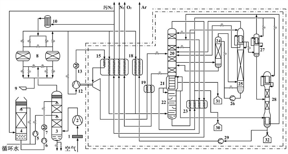
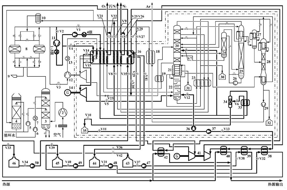
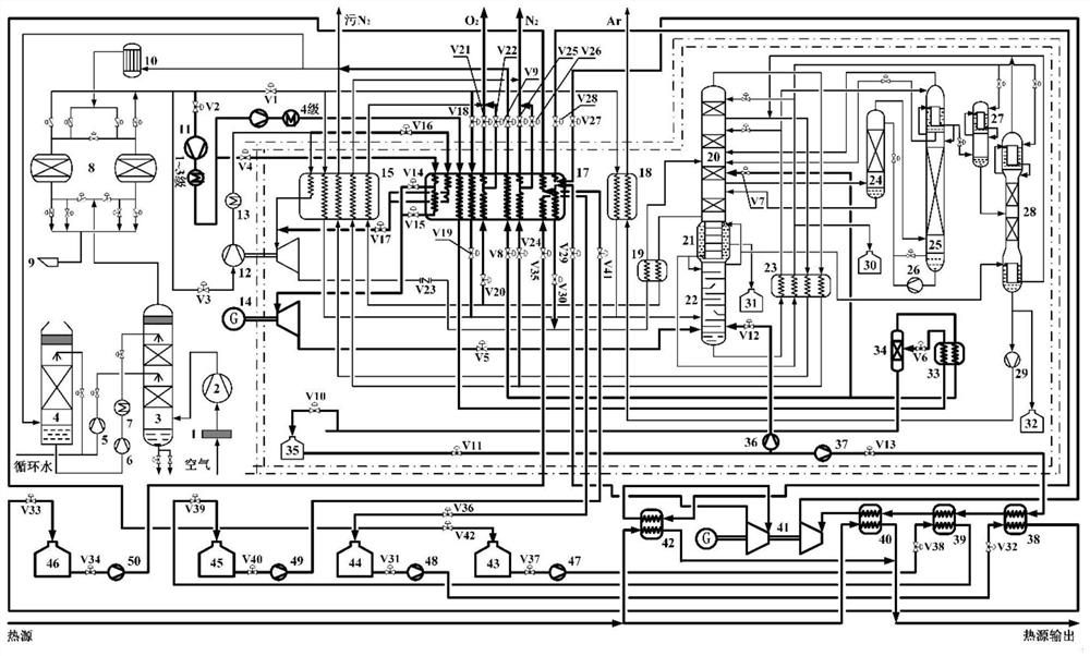
[0042] like figure 2 Shown is the oxygen production 40000Nm in the embodiment of the present invention 3 h -1 Schematic diagram of the air separation external compression process with the functions of energy storage, power generation and material recovery, replacing the medium-pressure main heat exchanger. During valley power storage, the raw air passes through the air filter 1 to remove dust and then enters the air compressor 2 for compression, and then enters the air cooling tower 3 for cooling and washing. The water used for cooling the air in the air cooling tower 3 has two parts: one part is for cooling The circulating water is pressurized by the cooling water pump 5 and sent to the middle part of the air cooling tower 3; the other part is chilled water, the circulating cooling water is initially cooled in the water cooling tower 4 by the dry dirty nitrogen and nitrogen from the rectification system, and then refrigerated The water pump 6 pressurizes, and is sent to th...


PUM


Abstract

The invention provides an external compression air separation technological process with energy storage, power generation and substance recovery functions, and belongs to the technical field of air separation. According to the process, a low-temperature liquid-air storage system and an air energy release power generation system are arranged on the basis of a conventional air separation external compression technological process, a new air separation technological process integrating gas separation, liquid-air storage, air power generation and substance recovery is formed, and the large-scale energy storage characteristic of air separation equipment and technology is achieved. The external compression air separation technological process is a new external compression air separation technological process, and is also suitable for upgrading and updating transformation of an existing air separation external compression technological process. According to the technological process, gas resources except for the air separation capacity requirement are liquefied and stored through cheap off-peak electricity resources, in the energy release period, by arranging cold accumulation circulationand utilizing compression waste heat, stored substances and cold energy released in the gasification process of low-temperature liquid air are fully recycled, electric energy is output, so that the requirement of the air separation equipment for electric energy in the peak electricity period is lowered, and the conomic benefits of enterprises are improved.

Description

technical field [0001] The invention relates to the field of air separation technology, in particular to an external compression air separation process flow with the functions of energy storage, power generation and material recovery. Background technique [0002] With the gradual increase in the proportion of electricity consumption by the tertiary industry and residents, as well as the increase in the uncertainty of electricity consumption, my country's power grid peak regulation is facing more and more severe challenges. Although new progress has been made in the research of wind power, photovoltaic and other technologies, the solution to the grid-connection problem of this intermittent renewable energy is still a long march for my country's and even the world's energy research. Therefore, the existence of abandoned wind and light will make my country's power grid peak shaving rely on thermal power units for a long time, and the frequent start and stop of thermal power un...

Claims


Application Information

Patent Timeline
IPC IPC(8): F01K25/10F01K13/00F01D13/00F01D15/10F25J3/04F25J5/00
CPCF01K25/10F01K13/00F01K13/006F01D13/00F01D15/10F25J5/00F25J3/04054F25J3/04109F25J3/04096F25J3/04157F25J3/04218F25J3/042F25J3/04296F25J3/04303F25J3/04393F25J3/04412F25J3/04678F25J3/04703F25J3/04727F25J2250/42F25J2250/58F25J3/04787F25J2245/40F25J2205/32F25J2205/34F25J3/04496F25J2235/02F25J3/04078F25J2205/04F25J3/04375F25J3/04224F25J2205/24F25J2240/90
Inventor 王立贺秀芬
Owner UNIV OF SCI & TECH BEIJING
Learn More