Flue gas cooler capable of adjusting flue gas flow speed on line

A flue gas cooler and flue gas flow rate technology, applied in the field of coal-fired power plant boilers, can solve the problems of flue gas cooler leakage, local ash accumulation blockage, fly ash viscosity, etc., to increase the flue gas flow rate and eliminate ash blockage Problems and solutions to the effect of excessively large flue gas flow rates

Pending Publication Date: 2021-02-09
XIAN THERMAL POWER RES INST CO LTD
View PDF0 Cites 1 Cited by
  • Summary
  • Abstract
  • Description
  • Claims
  • Application Information

AI Technical Summary

Problems solved by technology

In recent years, the flue gas coolers of many domestic coal-fired power plant units have been completely isolated due to large-scale leakage, and have to be replaced as a whole; some flue gas coolers have a large differential pressure on the flue gas side during operation, resulting in insufficient induced draft fan output, which affects load capacity
The main reason for the leakage of the flue gas cooler is that the high local flue gas flow rate causes wear and leakage. The reason for the high local flue gas flow rate is that most power plant flue gas coolers are retrofitted and installed after the unit is completed, which is limited by the original flue Arrangement, the straight section area in front of the heating is short, and the inlet flow field is difficult to achieve uniformity, resulting in excessively high local flue gas flow velocity in the flue gas cooler, resulting in wear and leakage
The main reason for the high differential pressure on the flue gas side of the flue gas cooler is the ash blockage problem in the flue gas cooler. There are three main reasons for the ash blockage: (1) The local flue gas flow rate is low or the concentration of fly ash in the flue gas is uneven (2) When burning high-sulfur coal or the denitrification system has a high ammonia escape rate and ammonium bisulfate deposits, the fly ash in the flue gas is more viscous and forms when the flue gas flows through the flue gas cooler. (3) The unreasonable structural position of the flue gas cooler causes dust accumulation. For example, the low-temperature economizer installed in the horizontal flue has more or less lower dust accumulation problems. The heat exchange tube adopts spiral finned tubes The flue gas cooler is easy to block ash
[0004] Aiming at the problems of flue gas cooler leakage and soot blockage, control is usually carried out by optimizing the flow field at the inlet of the flue gas cooler, controlling the escape of ammonia from the denitrification system, and strengthening the frequency of soot blowing in the flue gas cooler. However, due to the limitations of the layout location, and Changes in coal-fired sulfur content and decreased activity of denitrification catalysts cannot completely solve the problems of flue gas cooling leakage and ash blocking. gray problem

Method used


Image

  • Flue gas cooler capable of adjusting flue gas flow speed on line
  • Flue gas cooler capable of adjusting flue gas flow speed on line
  • Flue gas cooler capable of adjusting flue gas flow speed on line

Examples


Embodiment Construction

[0023] The present invention will be further described in detail below in conjunction with the accompanying drawings and embodiments.

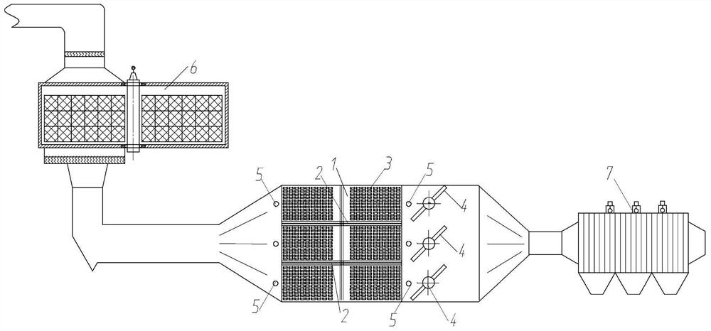
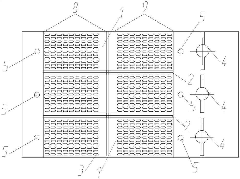
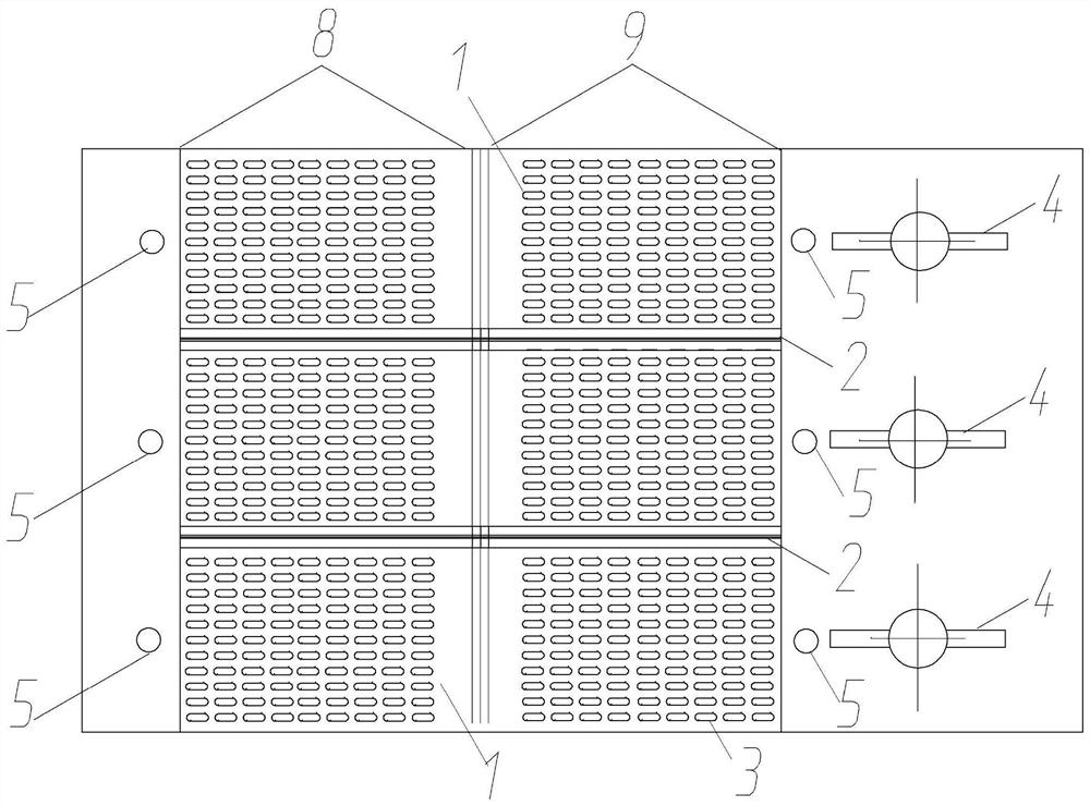
[0024] see Figure 1-4 , the flue gas cooler capable of adjusting the flue gas flow rate on-line in the present invention includes a shell and multiple sets of heat exchange modules 1 arranged inside the shell, and the shell is arranged between the air preheater 6 and the dust collector 7 of the coal-fired power plant boiler in the flue between. The heat exchange modules 1 are separated by flue plates 2. The heat exchange modules 1 are connected by several heat exchange tubes 3, and along the flow direction of the flue gas, an adjustable flue gas is installed behind the last heat exchange tube 3. Gas baffle 4. Each set of heat exchange modules 1 is provided with a pressure measuring point 5 at the front and rear respectively, and the number of pressure measuring points 5 is twice the number of heat exchange modules 1 . The flue gas cooler c...


PUM


Abstract

A flue gas cooler capable of adjusting the flue gas flow speed on line comprises a shell and multiple sets of heat exchange modules arranged in the shell. The heat exchange modules are separated through flue plates, each heat exchange module is formed by connecting multiple stages of heat exchange pipes, and an adjustable flue gas baffle is arranged behind the last stage of heat exchange pipe in the flue gas flow direction. A pressure measuring point is arranged at each of the positions in front of and behind each set of heat exchange module. According to the flue gas cooler, the flue gas flowin the sets of modules can be adjusted on line through changes of the opening degrees of the flue gas baffles, then the flue gas flow speed in the sets of modules is changed, ash blockage is eliminated by changing the flue gas flow speed, and meanwhile the differential pressure can be adjusted to a normal level.

Description

technical field [0001] The invention belongs to the field of coal-fired power station boilers, and in particular relates to a flue gas cooler capable of adjusting the flue gas velocity online. Background technique [0002] The flue gas cooler recovers the exhaust heat of coal-fired power plant boilers, which is used to heat condensate water, heat network return water, and fan inlet air temperature, so as to improve the overall economy of coal-fired power generation units and reduce coal consumption for power generation. The flue gas cooler is arranged in the flue between the boiler air preheater and the electrostatic precipitator, which reduces the temperature of the flue gas at the outlet of the air preheater from 120°C to 160°C to 90°C to 110°C, and the cooling medium (condensed water, Heating network return water) The inlet water temperature is above 70°C, and the outlet water temperature is above 95°C. [0003] Due to the small heat transfer temperature and pressure, in...

Claims


Application Information

Patent Timeline
IPC IPC(8): F23J15/02F23J15/06F23M9/00
CPCF23J15/025F23J15/06F23M9/003Y02E20/30
Inventor 杨辉党黎军党小建沈植张宇博贾明祥何未雨姚佳鑫
Owner XIAN THERMAL POWER RES INST CO LTD
Why Eureka
Try Eureka