
Ammonia injection grid for SCR denitration system

An ammonia injection grid and denitration technology, which is applied in the field of ammonia injection grid, can solve the problems of increasing the contact area of ​​flue gas, increasing the mixing time of ammonia flow and flue gas, and uneven distribution of ammonia gas, so as to reduce the by-products of ammonia injection. The generation of NOx, reducing the operating cost of denitration, and the effect of uniform NOX reaction

Pending Publication Date: 2021-02-26
SHANGHAI UNIVERSITY OF ELECTRIC POWER
View PDF0 Cites 1 Cited by
  • Summary
  • Abstract
  • Description
  • Claims
  • Application Information

AI Technical Summary

Problems solved by technology

The layout of the high-temperature and high-dust SCR denitrification system is conducive to saving investment and operating costs, but the disadvantage is that the flue gas contains a large amount of fly ash, which is easy to bond with the ammonium sulfate and ammonium bisulfate generated in the flue, and sticks to the On the surface of the equipment, some nozzles are blocked, which makes the distribution of ammonia gas uneven and the amount of local ammonia escape increases.
At present, the amount of ammonia sprayed on the branch pipe of the ammonia injection grid in the power plant is not uniform, and the uniform distribution of flue gas and ammonia gas when entering the catalyst layer cannot be guaranteed, and the denitrification efficiency is poor. To control the flow of each branch pipe, however, the ammonia injection volume of different nozzles on the same ammonia injection branch pipe cannot be adjusted, so that the desired effect cannot be achieved after the ammonia injection is adjusted. In addition, the outlet wind speed of the ammonia injection grid nozzle and the The mixing time of wind direction and flue gas also has a great influence on the mixing effect of ammonia gas and flue gas
[0004] However, there are still many deficiencies in the ammonia injection grid that can achieve dust prevention, flow regulation, and enhanced mixing effect in the patents that have been disclosed at present. A cap structure and a spiral airflow guide structure are added above the nozzle of the grid, which can change the ammonia flow from vertical upward to oblique diffusion at a certain angle, reduce the vertical velocity of the ammonia flow to a certain extent, and increase the ammonia flow and The mixing time of the flue gas, but this cap structure increases the accumulation of dust in the flue gas, which can easily cause ash accumulation and collapse. In addition, the accumulated dust and the ammonium sulfate and ammonium bisulfate generated by the side reactions in the flue gas will occur. Adhesion will cause dust to build up bridges on the edge of the nozzle, and long-term operation will block the nozzle
As well as the existing SCR flue gas denitrification and ammonia injection grid anti-blocking nozzles, the upper part of the tubular nozzle is provided with a double-layer umbrella cover to prevent the upper part of the grid from collapsing and blocking the nozzle, but the protruding brim structure increases The flue gas contact area does not take into account the wear of the umbrella cover, and the fixed air direction of the ammonia gas outlet is not conducive to flexible operation
[0005] An existing anti-blocking ammonia injection grid and SCR denitrification device adopts a spiral nozzle structure on the ammonia injection branch pipe, which can well prevent the dust accumulation from being broken by the tip of the spiral nozzle when the upper ash collapses. , scattered around, so as to avoid the problem of nozzle outlet clogging, but this structure also makes the mixing angle of ammonia gas and flue gas smaller, and the longitudinal section of the spiral nozzle in the structure reduces the outlet velocity of ammonia gas, which is not conducive to the mixing of flue gas and ammonia gas
[0006] In an existing ammonia injection grid, the rear control valve and the front control valve are used to control the ammonia injection volume of the rear connecting pipe and the front connecting pipe respectively, so that each ammonia spraying head sprays out the same amount of ammonia gas. This structure improves the In the past, the amount of ammonia sprayed on the branch pipe of the ammonia spray grid was not uniform, but the quantitative control of the sprayed ammonia volume did not have a good effect. Too little ammonia sprayed will easily cause the denitrification index to fail to meet the standard, and excessive ammonia sprayed will not increase. The operating cost will also have side reactions, which will have a negative impact on downstream equipment. In addition, the patent does not consider the impact of dust on the ammonia injection grid in the design of the nozzle.

Method used


Image

  • Ammonia injection grid for SCR denitration system
  • Ammonia injection grid for SCR denitration system
  • Ammonia injection grid for SCR denitration system

Examples


Embodiment 1

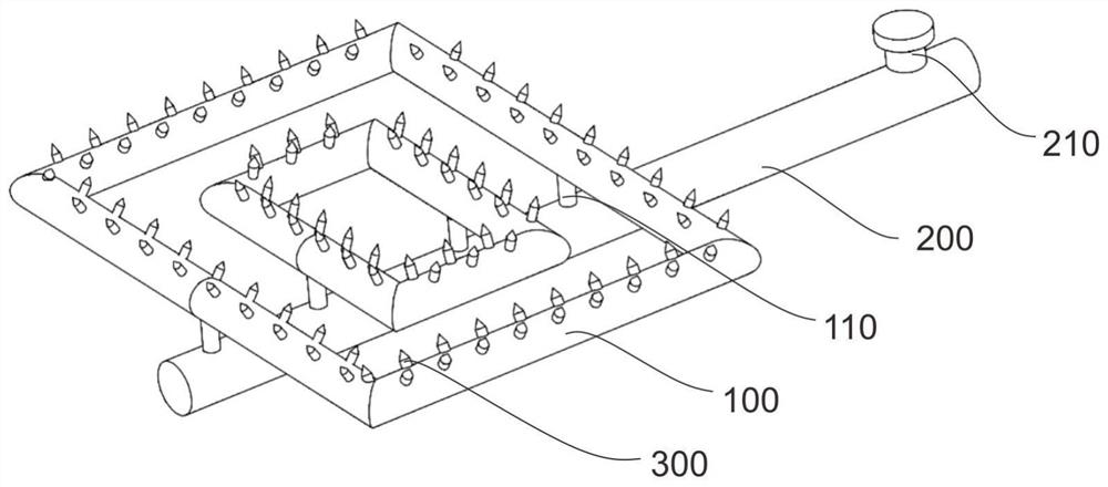
[0034] refer to figure 1, which is the first embodiment of the present invention, this embodiment provides an ammonia injection grid for SCR denitrification system, the ammonia injection grid for SCR denitrification system includes branch pipe assembly 100 and branch pipe assembly 200, wherein the branch pipe assembly 100 is arranged on the main pipe assembly 200 below the branch pipe assembly 100 through the connecting pipe 110. One end of the main pipe assembly 200 is provided with a control valve 210, and the branch pipe assembly 100 is arranged in a "back" shape;

[0035] The branch pipe assemblies 300 are evenly spaced and distributed on the upper surface of the branch pipe assembly 100 in a cross-staggered manner, and are arranged in high and low layers.

[0036] Based on the above, the branch pipe assembly 100 is arranged in a "back" shape, and the connecting pipe 110 is arranged vertically below the pipe branch assembly 100. The number of connecting pipes 110 is prefer...

Embodiment 2

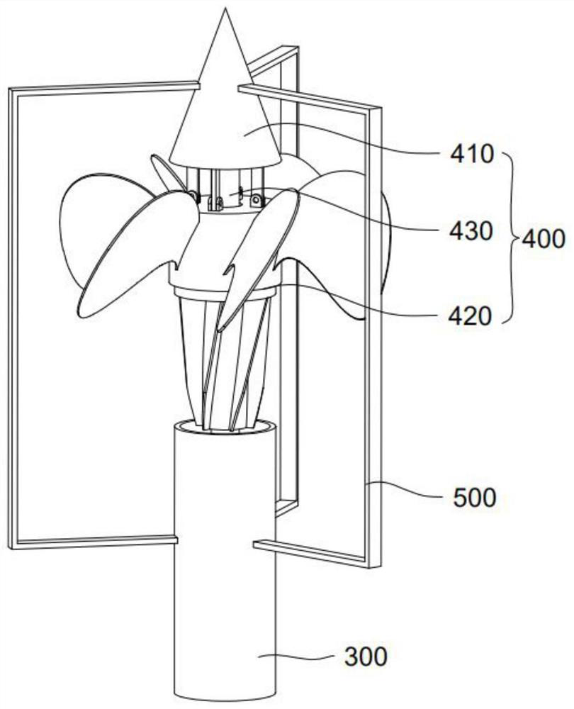
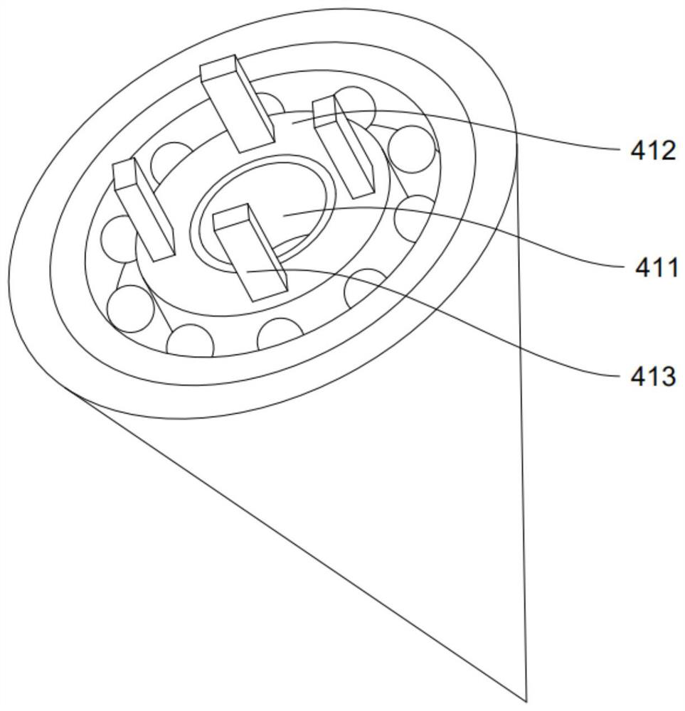
[0038] refer to Figure 2-5 , is the second embodiment of the present invention, which differs from the first embodiment in that: the branch pipe assembly 300 is provided with a vertebral body assembly 400, the vertebral body assembly 400 is provided with an upper vertebral body 410 and a lower vertebral body 420, and the upper vertebral body The body 410 is conical, the upper part is a tip, the diameter of the lower circular surface is larger than the pipe diameter of the branch pipe assembly 300, and the bottom is provided with a circular hole 411, and the inner surface of the circular hole 411 is provided with a thread groove, and the lower vertebral body 420 is arranged on the cylinder shaft 430. Below the upper vertebral body 410 .

[0039] Based on the above, the outer surface of the upper vertebral body 410 is smooth, and the tip is sharp, which can effectively break up the large pieces of dust that collapsed above, and the design of the smooth outer surface makes it di...


PUM


Abstract

The invention discloses an ammonia injection grid for an SCR denitration system, which is characterized in that adjacent branch pipe components on the ammonia injection grid are arranged in a crossedand staggered manner, and the branch pipe components on the same ammonia injection grid are arranged in a layered manner with a high middle part and a low periphery according to the characteristics ofhigh middle flow rate and low periphery flow rate of flue gas on the same section, so that the effective area of ammonia gas spraying can be enlarged, and the reaction between ammonia gas and NOX influe gas is more uniform; the sharp upper cone is arranged on the spray head of the branch pipe assembly, so that large collapsed dust blocks above can be effectively crushed, and dust is not prone todeposition due to the smooth outer surface design of the upper cone; the transverse blades and the longitudinal blades are arranged on the lower cone, wherein ammonia gas flow is changed into a certain angle from the vertical direction to obliquely rotate and diffuse, so that the mixing effect of the ammonia gas and NOX in the flue gas is enhanced; in addition, under the action of the telescopicrod and the lower cone, the ammonia gas flow at the outlet of the branch pipe assembly can be adjusted, and the nozzle is effectively prevented from being blocked by accumulated dust.

Description

technical field [0001] The invention relates to the technical field of power generation, in particular to an ammonia injection grid used in an SCR denitrification system. Background technique [0002] With the continuous development of social economy, the consumption of traditional fossil energy is increasing day by day, in order to reduce the emission and damage of toxic and harmful gases caused by the consumption of traditional fossil energy. According to the latest "Emission Standard of Air Pollutants for Boilers" (GB 13271-2014), the nitrogen oxide emission of boilers in use after April 1, 2017 should be ≤80mg / m 3 , the nitrogen oxide emission of newly built boilers is ≤30mg / m3. By the end of 2019, the coal power units that have reached the ultra-low emission limit are about 890 million kilowatts, accounting for about 86% of the total installed capacity of coal power in the country. Among them, SCR denitrification technology is adopted thermal power units account for mo...

Claims


Application Information

Patent Timeline
Patent Type & Authority Applications(China)
IPC IPC(8): B01D53/90B01D53/86B01D53/56
CPCB01D53/8631B01D53/90B01D2258/0283
Inventor 沈洪洪任建兴刘岗李芳芹顾群音任贵州刘育东陈梦萍王泽孙海杰
Owner SHANGHAI UNIVERSITY OF ELECTRIC POWER
Features
  • Generate Ideas
  • Intellectual Property
  • Life Sciences
  • Materials
  • Tech Scout
  • Unparalleled Data Quality
  • Higher Quality Content
  • 60% Fewer Hallucinations
Learn More