
Hydrogen-corrosion-preventing sealing device, hydrogen-corrosion-preventing motor and hydrogen circulating pump

A sealing device and hydrogen-proof technology, which is applied in the direction of pump devices, electromechanical devices, electrical components, etc., can solve the problems of sealing failure, motor stator corrosion, etc., and achieve the effect of good sealing, simple installation structure, and not easy to damage

Active Publication Date: 2021-03-26
BEIJING BOLKEN EQUIP +1
View PDF6 Cites 2 Cited by
  • Summary
  • Abstract
  • Description
  • Claims
  • Application Information

AI Technical Summary

Problems solved by technology

[0006] The invention provides an anti-hydrogen corrosion sealing device, an anti-hydrogen corrosion motor and a hydrogen circulation pump. The stator and rotor of the motor are isolated by setting a cone-shaped basin-shaped lining to solve the problem of the motor caused by the failure of the seal when the hydrogen circulation pump is pressurized. Stator Corrosion Problems

Method used


Image

  • Hydrogen-corrosion-preventing sealing device, hydrogen-corrosion-preventing motor and hydrogen circulating pump
  • Hydrogen-corrosion-preventing sealing device, hydrogen-corrosion-preventing motor and hydrogen circulating pump
  • Hydrogen-corrosion-preventing sealing device, hydrogen-corrosion-preventing motor and hydrogen circulating pump

Examples


Embodiment 1

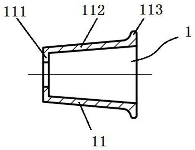
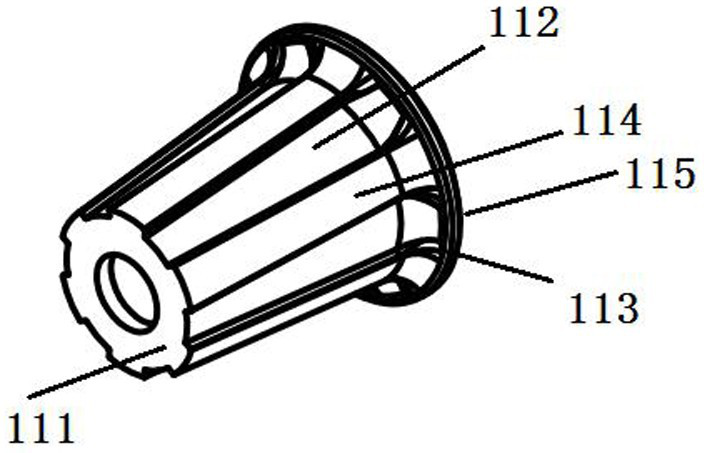
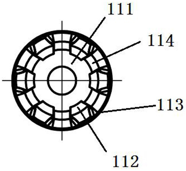
[0036] A hydrogen-corrosion-proof sealing device 1, as shown in Figure-3, includes a cone-shaped basin-shaped body made of hydrogen-corrosion-proof non-metallic composite materials (such as PEEK+30%GF polyether ether ketone+30% glass fiber material) 11. The tapered basin-shaped body 11 includes a basin bottom 111 , a conical portion 112 and an upper edge 113 , and the small-diameter side of the conical portion 112 (that is, the basin bottom 111 of the body) is sealed to form the basin bottom 111 , and the center of the bottom of the pot 111 has a hole so that the three shafts of the rotor of the motor can pass through smoothly; Its large diameter side extends outward along its radial direction.

[0037] Preferably, the taper of the tapered portion 112 of the body 11 is no more than 5 degrees, and the surface of the tapered portion 112 along its axial direction is provided with a rib 114 that fits into the notch 215 of the stator 2 . Such as figure 1 The six ribs 114 shown ar...

Embodiment 2

[0041] A hydrogen corrosion-resistant motor, such as Figure 4-5 As shown, the stator 2 and the rotor 3 of the motor are isolated by using the above-mentioned hydrogen corrosion prevention sealing device 1. The hydrogen corrosion prevention sealing device 1 is now an anti-hydrogen corrosion lining, and its basin bottom 111 passes through the first A sealing positioning protrusion 1151 cooperates with the front positioning groove provided by the motor front end cover 4 to realize sealing positioning, and the upper edge 113 is connected with the rear end of the motor through the second sealing positioning protrusion 1152 provided thereon. The cover 7 is hermetically positioned, and the stator 2 is isolated in a closed space formed by the hydrogen corrosion prevention sealing device 1 and the casing 6 of the motor.

[0042] Inside the anti-hydrogen corrosion motor, the hydrogen gas overflowing into the motor through the booster pump chamber only exists in the anti-hydrogen corros...

Embodiment 3

[0047] A hydrogen circulation pump, using the above-mentioned anti-hydrogen corrosion motor as a power source, and the part where the shaft of the rotor 3 of the hydrogen corrosion prevention motor protrudes from the motor casing 6 is connected with the circulation impeller of the hydrogen gas circulation pump.


PUM


Abstract

The present invention provides a hydrogen circulating pump, a hydrogen corrosion prevention sealing device is made of an insulated hydrogen corrosion prevention nonmetal synthetic material into a conical basin-shaped body, and a stator and a rotor of a hydrogen corrosion prevention motor are separated, that is, hydrogen overflowing from the hydrogen circulating pump to the hydrogen corrosion prevention motor is isolated from the stator; a hydrogen corrosion prevention lining is simple in installation structure; and a cone-shaped basin-shaped structure can be adopted to ensure strength, deformation caused by rotation of a stator magnetic circuit and a rotor is avoided, and meanwhile magnetic field conversion between the stator and the rotor is not affected. The hydrogen corrosion preventionmotor uses the hydrogen corrosion prevention sealing device, so that the risk of electric sparks generated by stator voltage arc discharge is reduced. And the stator adopts H-shaped structure teeth,so that the torque and the rotating speed which are twice those of the traditional tooth-shaped stator structure can be obtained, and the material consumption is small.

Description

technical field [0001] The invention relates to the technical field of motor sealing, in particular to a hydrogen corrosion preventing sealing device, a hydrogen corrosion preventing motor and a hydrogen circulation pump. Background technique [0002] During the reaction process of the fuel cell, the hydrogen molecules at the anode are generally decomposed into two protons (proton) and two electrons (electron) through the action of a catalyst. After the circuit forms the current, it reaches the cathode. After the fuel cell reaction, there will be a part of the hydrogen that has not been converted. The discharge of this flammable and explosive gas into the air is not only a waste of energy but also greatly reduces the energy conversion efficiency of the hydrogen fuel cell system. With the development of hydrogen fuel cell systems for new energy vehicles, the energy conversion efficiency requirements of fuel cell vehicles are getting higher and higher, and the recycling of hy...

Claims


Application Information

Patent Timeline
Patent Type & Authority Applications(China)
IPC IPC(8): H02K5/12H02K3/34H02K1/14H02K7/14F04D29/08F04D25/06
CPCF04D25/06F04D29/083H02K1/146H02K3/345H02K5/12H02K7/14
Inventor 赵洪洋徐子介张璇肖育民
Owner BEIJING BOLKEN EQUIP
Learn More