Optical coherence imaging system capable of reducing optical path dispersion and imaging method

An optical coherent imaging and imaging system technology, applied in the field of optical coherent imaging systems, can solve the problems of reducing the accuracy of imaging and surgical safety, contradicting the purpose of high-precision measurement, reducing signal strength and signal-to-noise ratio, etc., to achieve reduction Performance requirements, reducing real-time difficulty and cost, and improving imaging signal strength and signal-to-noise ratio

Inactive Publication Date: 2021-04-02
JIHUA LAB
View PDF4 Cites 0 Cited by
  • Summary
  • Abstract
  • Description
  • Claims
  • Application Information

AI Technical Summary

Problems solved by technology

[0003] The current technical solution uses natural light for measurement, which is affected by stray light in the environment, and it is easy to introduce imaging errors, which is contrary to the purpose of high-precision measurement
When the optical coherent imaging system that can reduce optical path dispersion is detected, crosstalk is prone to occur, and it is easily interfered by stray light in the natural environment, which greatly reduces the signal strength and signal-to-noise ratio, and reduces the accuracy of imaging and the safety of surgery.

Method used


Image

  • Optical coherence imaging system capable of reducing optical path dispersion and imaging method

Examples


Embodiment 1

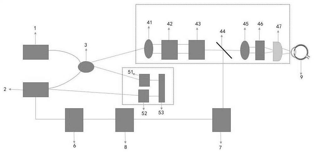
[0033] see figure 1 , is a schematic structural diagram of an optical coherent imaging system capable of reducing optical path dispersion provided in Embodiment 1 of the present application, including: a light source (1), a detection unit (2), an interferometer (3), an image beam transmission unit (4), and a reference beam transmission unit (5), data collection and analysis unit (6), control unit (7) and image display unit (8); the image beam transmission unit (4) includes sequentially connected first collimating lenses (41) , a polarization coupler (42), a two-dimensional galvanometer scanning unit (43), a dichroic mirror (44), a second collimating lens (45), a dispersion compensator (46) and a focusing lens (47), the The reference beam transmission unit (5) includes a first polarizer (51), a second polarizer (52) and a mirror (53).

[0034] In some of these embodiments, the fiber polarizing unit (10) is a dichroic polarizer.

[0035] It can be understood that the polarizer...

Embodiment 2

[0053] The present application also provides an imaging method of an optical coherent imaging system capable of reducing optical path dispersion, comprising the following steps:

[0054] Step S110: the scanning wavelength beam generated by the light source (1) is divided into an image beam and a reference beam by the interferometer (3);

[0055] Step S120: the reference beam enters the first polarizer (51), the second polarizer (52) and the mirror (53) sequentially through the optical fiber transmission line 9, and the reference beam is then return to the interferometer (3) through the mirror (53), the second polarizer (52) and the first polarizer (51) in sequence

[0056] Step S130: the image beam sequentially passes through the first collimator lens (41), the polarization coupler (42), the two-dimensional galvanometer scanning unit (43), and the dichroic mirror (44) , the second collimating lens (45), the dispersion compensator (46) and the focusing lens (47) gather at the ...


PUM


Abstract

The invention provides an optical coherence imaging system capable of reducing optical path dispersion and an imaging method, and the system comprises a light source (1), a detection unit (2), an interferometer (3), an image beam transmission unit (4), a reference beam transmission unit (5), a reference beam transmission unit (5), a data collection and analysis unit (6), a control unit (7), and animage display unit (8). According to the optical coherence imaging system capable of reducing optical path dispersion, a polarized light imaging technology is adopted, the optical coherent imaging system capable of coordinating work and reducing optical path dispersion is constructed by using an optical fiber polarizer and a polarization coupler, interference of stray light in the natural environment is not likely to happen, dispersion of the whole optical path is reduced, and the requirement for the optical fiber dispersion performance is greatly lowered; the implementation difficulty and cost of the technical scheme are reduced, the imaging signal intensity and the signal-to-noise ratio are improved, and the detection accuracy and the operation implementation safety are improved.

Description

technical field [0001] The invention belongs to the technical field of medical devices, and in particular relates to an optical coherent imaging system and an imaging method capable of reducing optical path dispersion. Background technique [0002] Optical coherence tomography has the characteristics of non-contact, no radiation, high detection sensitivity, and no damage. Optical coherence tomography has become a standard technique for measuring the structure of the human eye in ophthalmic surgery. Femtosecond laser-assisted ophthalmic surgery is an ophthalmic surgery that uses femtosecond laser pulses, optical coherence tomography technology for high-precision detection, and computer precision calculations for trajectory planning to automate and intelligentize several key steps in traditional ophthalmic surgery. . Before, during and after surgery, it is necessary to accurately scan the position and contour of the eye tissue and display the image to the doctor. [0003] Th...

Claims


Application Information

Patent Timeline
IPC IPC(8): G02B27/28G02B27/00
CPCG02B27/0031G02B27/286
Inventor 周辉
Owner JIHUA LAB
Why Eureka
Try Eureka