Large-field-angle eyepiece optical system and head-mounted display device

An optical system and display device technology, applied in the optical field, can solve problems such as bulkiness, distortion spherical aberration, etc., achieve the effects of small volume, system aberration elimination, and improved visual comfort experience

Pending Publication Date: 2021-04-09
SHENZHEN NED OPTICS CO LTD
View PDF5 Cites 5 Cited by
  • Summary
  • Abstract
  • Description
  • Claims
  • Application Information

AI Technical Summary

Problems solved by technology

[0004] The Fresnel structure that patent document 1 (Chinese Patent Publication No. CN109416469A), Patent Document 2 (Chinese Patent Publication No. CN105759424B), Patent Document 3 (Chinese Patent Publication No. CN107015361B), and Patent Document 4 (Chinese Patent Publication No. CN111381371A) adopt respectively Although good focusing effects can be achieved in the optical system, Patent Document 1 and Patent Document 3 completely rely on Fresnel lenses, while Patent Document 2 and Patent Document 4 are based on Fresnel lenses and single-element or double-element positive lenses. Combination, it is inevitable that it is difficult to make achievements in the aberration of the optical system, there is a lot of distortion and spherical aberration
[0005] What Patent Document 5 (Chinese Patent Publication No. CN105278109A) provides is to have adopted the optical system of combination of positive, negative and positive lens groups. What is provided is the optical system that has adopted the combination of positive, negative and positive lens groups. It is a traditional spherical and even-order aspheric optical system. Although it has great advantages in aberration correction, it is extremely bulky under the same optical system parameters.

Method used


Image

  • Large-field-angle eyepiece optical system and head-mounted display device
  • Large-field-angle eyepiece optical system and head-mounted display device
  • Large-field-angle eyepiece optical system and head-mounted display device

Examples


no. 1 example

[0085] The eyepiece design data of the first embodiment are shown in Table 1 below:

[0086] Table I

[0087]

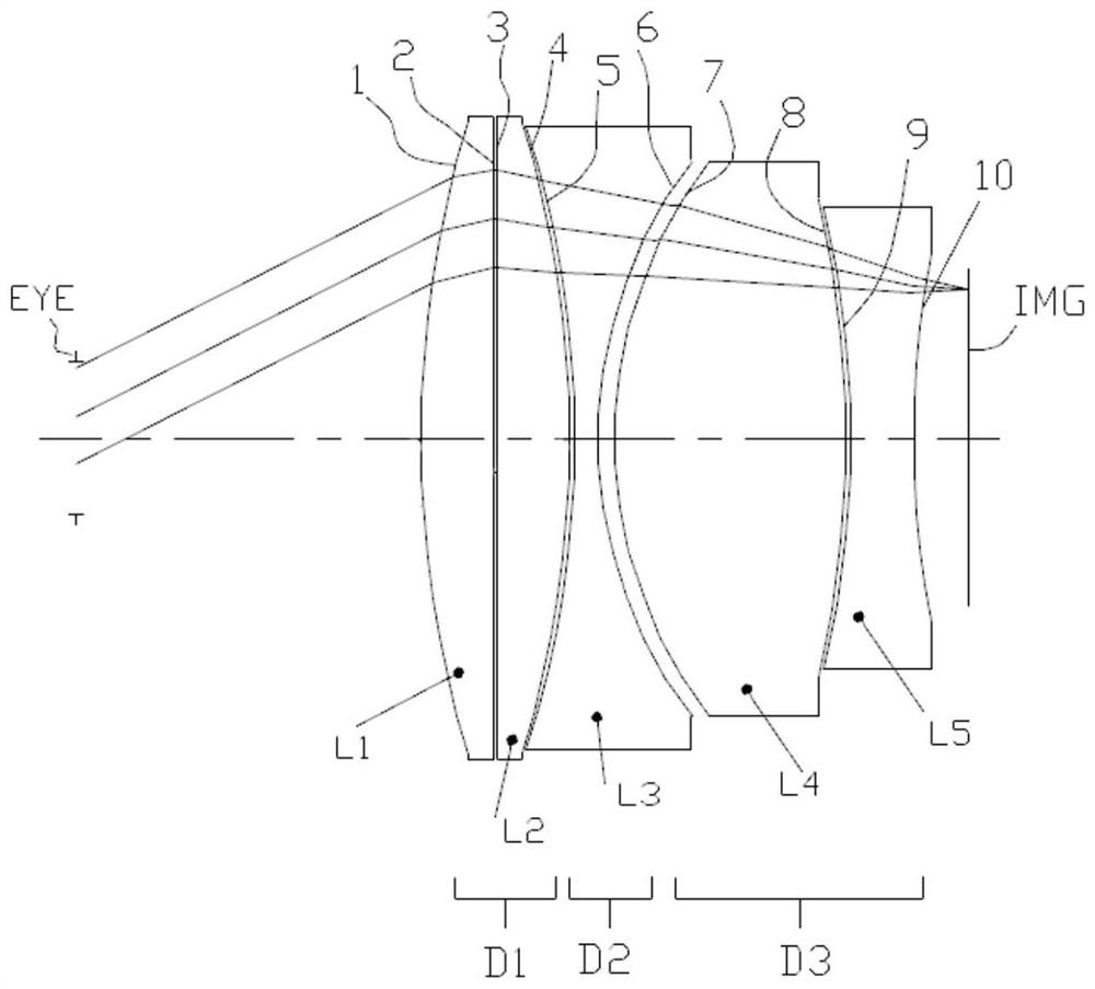
[0088] attached figure 1It is a 2D structural diagram of the eyepiece optical system of the first embodiment, including the first lens group D1, the second lens group D2 and the third lens arranged coaxially along the optical axis from the human eye observation side to the display device (IMG) side Group D3, the first lens group D1 includes the first lens L1 and the second lens L2; ​​the optical surface 2 and the optical surface 3 in the first lens L1 and the second lens L2 are Fresnel surfaces arranged adjacently, and the second Lens group D2 is a negative effective focal length lens group composed of a negative effective focal length optical lens, including a third lens L3 respectively; the third lens group D3 is a positive effective focal length optical lens composed of a positive effective focal length optical lens and a negative effective focal length optica...

no. 2 example

[0091] The eyepiece design data of the second embodiment are shown in Table 2 below:

[0092] Table II

[0093]

[0094] attached Figure 5 It is a 2D structural diagram of the eyepiece optical system of the second embodiment, including the first lens group D1, the second lens group D2 and the third lens arranged coaxially along the optical axis from the human eye observation side to the display device (IMG) side Group D3, the first lens group D1 includes the first lens L1 and the second lens L2; ​​the optical surface 2 and the optical surface 3 in the first lens L1 and the second lens L2 are Fresnel surfaces arranged adjacently, and the second Lens group D2 is a negative effective focal length lens group composed of a negative effective focal length optical lens, including a third lens L3 respectively; the third lens group D3 is a positive effective focal length optical lens composed of a positive effective focal length optical lens and a negative effective focal length o...

no. 3 example

[0097] The eyepiece design data of the third embodiment are shown in Table 3 below:

[0098] Table three

[0099]

[0100]

[0101] attached Figure 9 It is a 2D structural diagram of the eyepiece optical system of the third embodiment, including the first lens group D1, the second lens group D2 and the third lens arranged coaxially along the optical axis from the human eye observation side to the display device (IMG) side Group D3, the first lens group D1 includes the first lens L1 and the second lens L2; ​​the optical surface 2 and the optical surface 3 in the first lens L1 and the second lens L2 are Fresnel surfaces arranged adjacently, and the second Lens group D2 is a negative effective focal length lens group composed of a negative effective focal length optical lens, including a third lens L3 respectively; the third lens group D3 is a positive effective focal length optical lens composed of a positive effective focal length optical lens and a negative effective f...


PUM


Abstract

The invention relates to a large-field-angle eyepiece optical system and a head-mounted display device, and the system comprises a first lens group, a second lens group and a third lens group, which are coaxially and sequentially arranged from a human eye observation side to a miniature image display side in the direction of an optical axis. The effective focal lengths of the first lens group, the second lens group and the third lens group are positive, negative and positive combinations; the first lens group comprises a first lens close to the human eye side and a second lens far away from the human eye side; the first lens group comprises at least two Fresnel optical surfaces; the first lens comprises at least one Fresnel optical surface; the second lens group comprises third lenses which are adjacent to the first lens group and are sequentially arranged along the optical axis; the third lens is a negative lens; the third lens group comprises a fourth lens and a fifth lens which are adjacent to the second lens group and are sequentially arranged along the optical axis; the fourth lens is a positive lens; the fifth lens is a negative lens; and the system can realize the indexes of large field angle, high image quality, low distortion, small field curvature, small volume and the like.

Description

technical field [0001] The invention relates to the field of optical technology, more specifically, to an eyepiece optical system with a large viewing angle and a head-mounted display device. Background technique [0002] With the continuous development of electronic devices towards ultra-miniaturization, as well as the development of new computer, microelectronics, optoelectronic devices and communication theories and technologies, wearable computing, a new model based on "people-oriented" and "integration of man and machine" has become possible. . Applications are emerging in military, industrial, medical, education, consumer and other fields. In a typical wearable computing system architecture, the head-mounted display device is a key component. The head-mounted display device guides the video image light emitted by the micro-image display (such as transmissive or reflective liquid crystal display, organic electroluminescent device, DMD device) to the user's pupil throu...

Claims


Application Information

Patent Timeline
Patent Type & Authority Applications(China)
IPC IPC(8): G02B27/01G02B25/00G02B3/08G02B3/02
CPCG02B3/02G02B3/08G02B25/001G02B27/0172
Inventor 曹鸿鹏郭健飞彭华军
Owner SHENZHEN NED OPTICS CO LTD
Why Eureka
Try Eureka