

Laser joule composite heat source metal filament additive manufacturing device and method
A technology of metal filaments and composite heat sources, which is applied in the direction of manufacturing tools, additive processing, laser welding equipment, etc., can solve the problems of expensive metal powder, low peak temperature in the forming area, poor stability and precision, etc., to improve energy Utilization rate, reducing temperature gradient, and improving the effect of wire feeding accuracy
Pending Publication Date: 2021-04-13
NAT INST CORP OF ADDITIVE MFG XIAN
View PDF7 Cites 0 Cited by
- Summary
- Abstract
- Description
- Claims
- Application Information
AI Technical Summary
Problems solved by technology
The molding precision of powder-based additive manufacturing technology is relatively high, and the development is relatively fast, but its material utilization rate is very low (the material utilization rate is only 20% to 30%), the price of metal powder is relatively expensive, and the powder particles are harmful to the environment. There are certain hazards to the operator, and the heat sources used in the powder-based additive manufacturing technology are mainly laser and electron beam.
According to different heat sources, the common ones are wire and laser additive manufacturing (WLAM), electron beam freeform fabrication (EBF3) and wire and arc additive manufacturing. , WAAM), etc., the material utilization rate of wire-feed additive manufacturing is close to 100%, the cost of metal wire is lower, and the molding process is safer, but its molding quality is relatively poor
Due to the high control precision, laser as a heat source is the most popular research method, but its energy utilization rate is very low (2% to 5%); the energy utilization rate of electron beam is slightly increased (15% to 20%), However, it requires a high vacuum environment, and the requirements for the equipment are relatively strict; the energy utilization rate of the arc process is as high as 70%, but the arc equipment is often huge, accompanied by a lot of noise and arc pollution, because the arc is difficult to control accurately, the surface of the formed part is uneven Uneven, poor forming accuracy, can not be used directly, must be reduced before equipment
Complex molding process
Direct high-energy beam additive manufacturing equipment is expensive, complex, bulky, and radiation-polluted
The energy utilization rate of Joule heat molten metal forming is close to 100%, and the mechanism is simple. It directly heats the wire material for melting and forming through electric current, but because the energy is not concentrated enough, the peak temperature of the forming area is low, so it is difficult to realize the combination of single pass and substrate and Combine layers
At present, there are few studies on filament delivery. Due to the relatively poor stiffness of filaments, deflection and bending are easy to occur during the delivery process, resulting in the inability of the filaments to be accurately delivered to the corresponding positions, thereby affecting the laser spot and Wire alignment, resulting in poor stability and accuracy of molding
Method used
View moreImage
Smart ImageViewing Examples

Examples
Embodiment
[0085] This application adopts the method of the present invention to print thin-walled parts, and carries out the experiment (length 40mm) of 150 layers of large-scale thin-walled parts forming with wire feeding ratio as 1, as Figure 6 shown.
Login to View More PUM
| Property | Measurement | Unit |
|---|---|---|
| Surface roughness | aaaaa | aaaaa |
| Tensile strength | aaaaa | aaaaa |
| Micro vickers hardness | aaaaa | aaaaa |
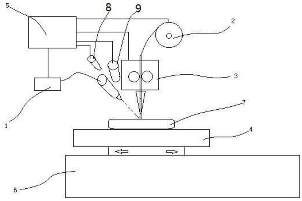
Abstract
The invention discloses a laser joule composite heat source metal filament additive manufacturing device and method. A laser device, a filament feeding mechanism, a joule heating device, a forming base plate and a controller are utilized to form the laser joule composite additive manufacturing device, and a joule heating device is arranged at the upper end of the forming base plate. A filament feeding port of the filament feeding mechanism is aligned with a filament inlet of the joule heating device, filaments are fed into the joule heating device through the filament feeding mechanism to be heated and then reach the forming base plate, and filaments discharged from a heating point of the laser device and a wire outlet of the joule heating device are both located on to-be-formed points. After the filaments are electrified with current, the filaments are heated to the temperature close to the melting point under the action of joule heat, part of heat is provided through laser assistance to melt the filaments, a molten pool is formed in the surface of the base plate or the surface of the previous layer, metallurgical bonding is formed, the electric energy can be effectively utilized, the power of needed lasers is reduced, and the overall energy utilization rate is increased.
Description
technical field [0001] The invention relates to the field of metal additive manufacturing, in particular to a laser Joule composite heat source metal filament additive manufacturing device and method. Background technique [0002] Additive manufacturing (additive manufacturing, AM) technology is a technology based on CAD / CAM design, using a layer-by-layer accumulation method to manufacture solid parts. Compared with traditional subtractive manufacturing (cutting) technology, it is a kind of material accumulation manufacturing method. Additive manufacturing technology, commonly known as 3D printing technology, is an advanced manufacturing technology that has developed rapidly in the past 30 years. Its advantage lies in the rapid and free manufacturing of three-dimensional structures, and it is widely used in new product development and single-piece small-batch manufacturing. Among them, metal direct forming is a difficult and hot technology in additive manufacturing technolo...
Claims
Login to View More Application Information
Patent Timeline
 IPC IPC(8): B23K26/34B23K26/211B23K26/70B33Y10/00B33Y30/00
CPCB23K26/34B23K26/211B23K26/702B33Y10/00B33Y30/00
Inventor李波波卢秉恒朱刚李晓强孔降宇
OwnerNAT INST CORP OF ADDITIVE MFG XIAN