
Grain drying dehumidifying heat pump unit and grain drying circulation heat pump system

A technology of grain drying and heat pump system, applied in dryers, drying gas arrangement, drying and other directions, can solve the problems of difficulty in starting the system, limited energy saving, decreased drying efficiency, etc. Too high, the effect of preventing the supply air temperature from being too high

Pending Publication Date: 2021-04-27
徐玉斌
View PDF0 Cites 4 Cited by
  • Summary
  • Abstract
  • Description
  • Claims
  • Application Information

AI Technical Summary

Problems solved by technology

Combustion of hot air to heat the air for grain drying has the advantages of low cost, but the disadvantages are (1) serious pollution, poor production environment, and high labor intensity of workers. The air pollution is mainly composed of fuel combustion and dry grain dusty exhaust. ; (2) The instability of the hot air temperature has an adverse effect on the quality of the grain; (3) Storage facilities for fuel and ash after combustion are required; (4) The combustion of the hot air stove has high safety requirements
In some areas with high environmental protection requirements in our country, there are also grain drying devices using clean energy such as natural gas and fuel oil. Although the combustion pollution is relatively reduced, there are the following disadvantages: (1) The dusty air of the dry grain exhaust is still discharged to the atmosphere, and the fuel Greenhouse gas emissions from combustion affect the atmospheric environment; (2) The unit price of fuel is high, resulting in high production costs; (3) There is no pipeline natural gas source in some areas, and the choice is limited; (4) Since natural gas and fuel oil are flammable and explosive items, there are potential safety hazards, and there are many related construction projects and transportation approval processes; (5) There is also a certain risk of pollution when the air directly heats food after fuel combustion
Although this method has less impact on the environment than the combustion method and has a certain energy-saving effect, it has the following problems: ①Limited energy saving: since the fresh air needs to be directly heated to the set temperature, when the fresh air temperature is low (such as 10°C Below), the energy saving of the system is limited; ②Unstable output: when the fresh air temperature is low, the drying efficiency drops sharply; ③Cannot be used in cold areas: although an auxiliary electric heater is installed, the system is difficult to start when the fresh air temperature is low; ④Low utilization rate of equipment: the evaporator of the heat pump device exchanges heat with the fresh air, and the evaporator will frost. During defrosting, some compressors of the heat pump unit cannot provide heat to heat the air; ⑤There is still dusty air discharged into the atmosphere
However, the regenerative heat pump drying method also has some problems of the direct current heat pump method, but the degree is relatively minor.

Method used


Image

  • Grain drying dehumidifying heat pump unit and grain drying circulation heat pump system
  • Grain drying dehumidifying heat pump unit and grain drying circulation heat pump system
  • Grain drying dehumidifying heat pump unit and grain drying circulation heat pump system

Examples


Embodiment Construction

[0021] In the following description, numerous specific details are given in order to provide a more thorough understanding of the present invention. It will be apparent, however, to one skilled in the art that the present invention may be practiced without one or more of these details. In other examples, some technical features known in the art are not described in order to avoid confusion with the present invention.

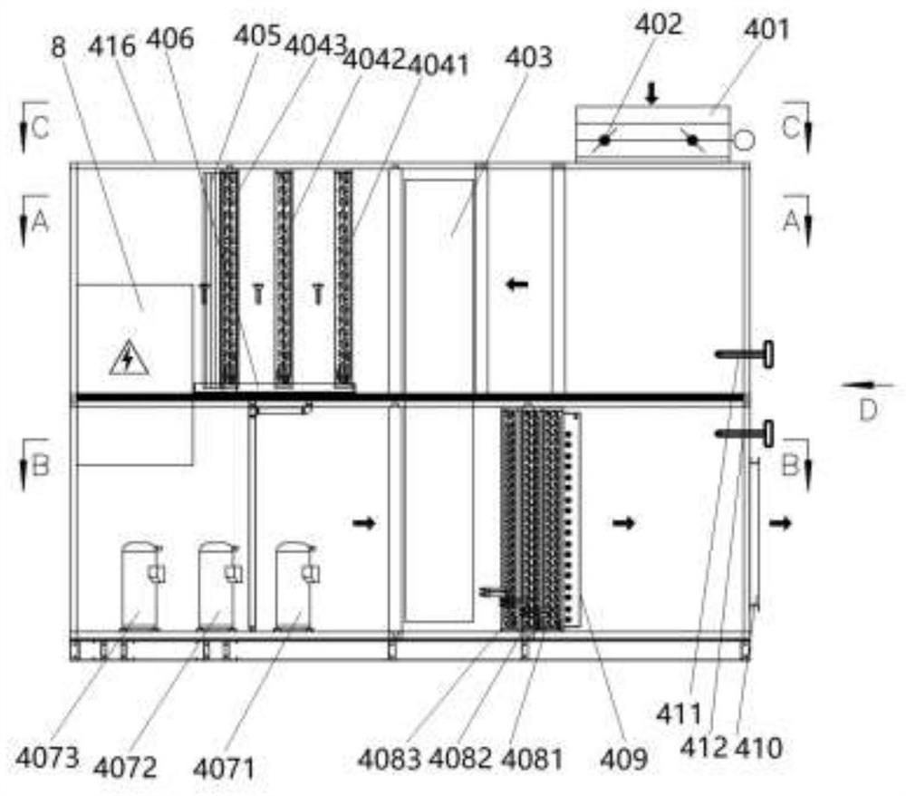
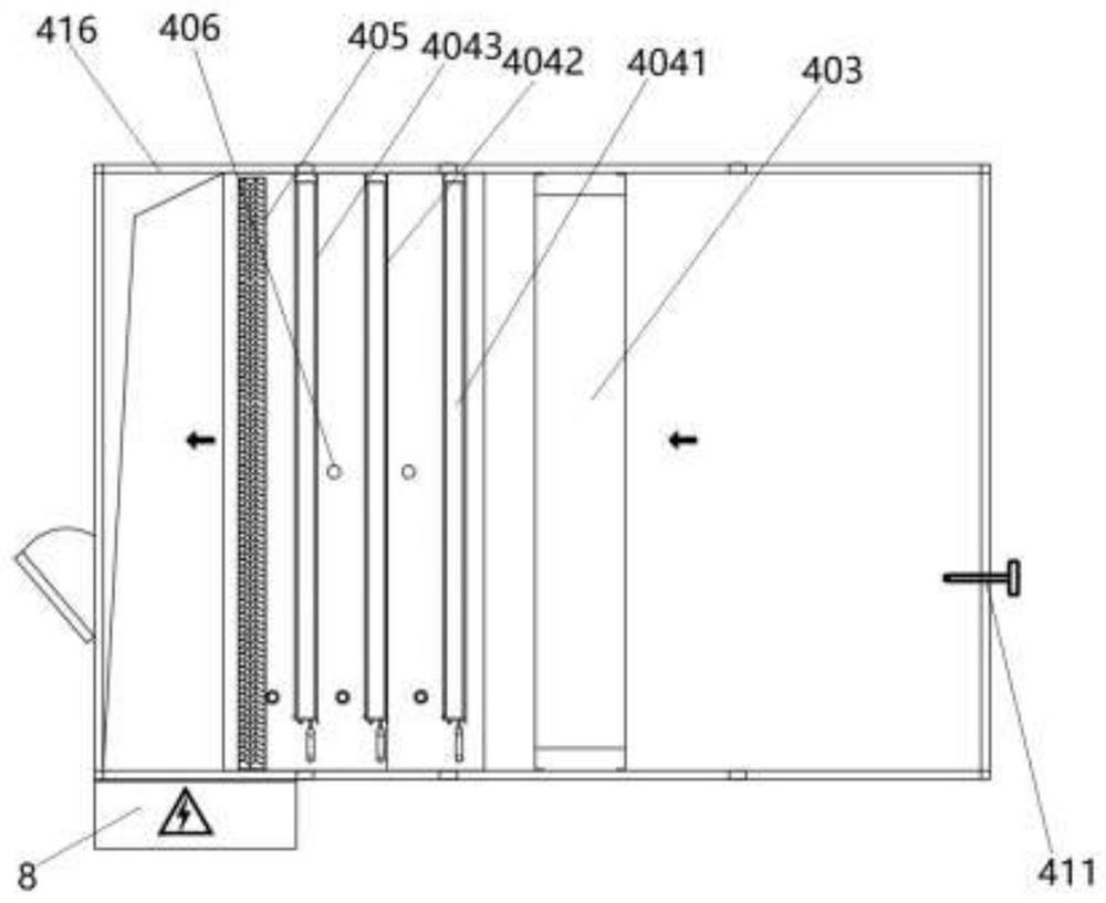
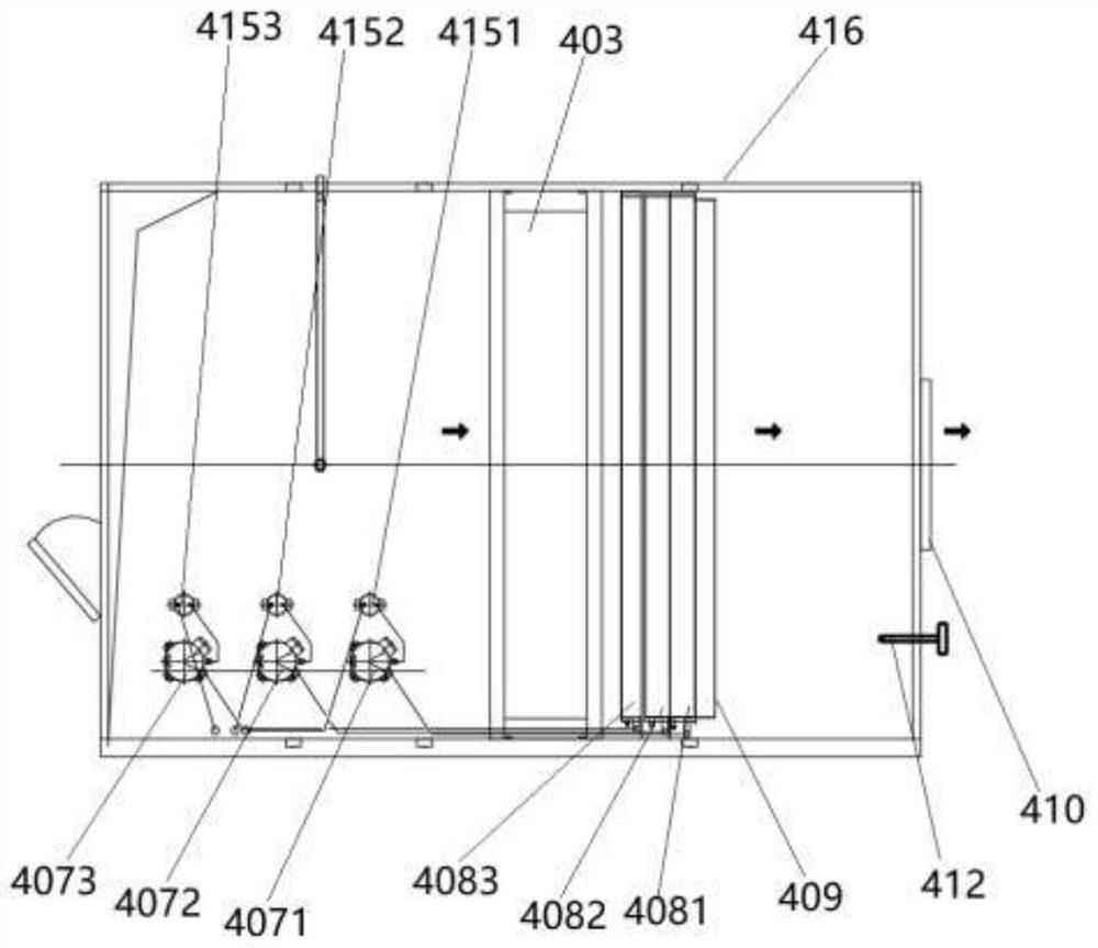
[0022] Such as Figure 1 to Figure 3As shown, the grain drying and dehumidifying heat pump unit 4, hereinafter referred to as "the device". The device includes an upper and lower layered chassis 416, three sets of independently working heat pump systems installed in the chassis 416, an air inlet 401, an electric air inlet valve 402, an inlet air temperature and humidity sensor 411, and a sensible heat rotary heat exchanger 403, water baffle 405, condensed water tray and water pipe 406, auxiliary electric heater 409, air supply port 410, air supply temperature ...


PUM


Abstract

The invention discloses a grain drying dehumidifying heat pump unit and a grain drying circulation heat pump system, and belongs to the field of drying dehumidifying equipment. Three independent heat pump systems and a sensible heat type runner heat exchanger are installed in a dehumidifying heat pump unit box body, a cooling dehumidifying part is installed in an upper layer box body, an air inlet end is connected with an air inlet section of the unit, and an air outlet end is connected with evaporators; and a heating part is mounted in a lower layer box body, an air inlet end is connected with compressor sections of the unit, and an air outlet end is connected with air cooling condensers. In the grain circulation heat pump drying system, the dehumidifying heat pump unit is in hot air connection with a batch type grain dryer, the batch type grain dryer is connected with a precision dust remover, the precision dust remover is connected with a circulation fan, and an outlet of the circulation fan is connected with the dehumidifying heat pump unit and an exhaust pipe. The unit and the system are environmentally friendly, energy-saving and emission-reducing, and are efficient and stable in operation, the cost is reduced, the unattended automatic operation can be realized, good quality of dried grains can be guaranteed, then the application region of the heat pump system for grain drying is expanded, and the developing of low-temperature drying of grains is embodied.

Description

technical field [0001] The invention belongs to the field of drying and dehumidifying equipment, and in particular relates to a grain drying and dehumidifying heat pump unit and a grain drying circulation heat pump system. Background technique [0002] High-moisture grains are mostly dried with hot air, and the hot air heating energy is mostly coal, biomass, natural gas, fuel oil, etc. The environmental protection issues and operating costs have always been concerned by the government, enterprises and the public. At present, the heat source of grain drying mainly uses coal and biomass as fuel. Combustion of hot air to heat the air for grain drying has the advantages of low cost, but the disadvantages are (1) serious pollution, poor production environment, and high labor intensity of workers. The air pollution is mainly composed of fuel combustion and dry grain dusty exhaust. (2) The instability of the hot air temperature will have an adverse effect on the quality of the gra...

Claims


Application Information

Patent Timeline
Patent Type & Authority Applications(China)
IPC IPC(8): F26B21/00F26B21/04F26B21/08F26B21/10
CPCF26B21/04F26B21/003F26B21/10F26B21/08
Inventor 徐玉斌戴亚俊王夏昕黄海生裘骏凯赵彩兰王广辉刘兴勇
Owner 徐玉斌
Learn More