Pulse wave monitoring device and method based on optical fiber sensing

An optical fiber sensing and monitoring device technology, applied in sensors, pulse rate/heart rate measurement, diagnostic recording/measurement, etc., can solve the characteristics that cannot reflect the evolution of pulse waveform, pulse wave velocity variation law, ultrasonic technology background noise influence, low frequency The response is not good enough to achieve the effect of being conducive to rapid positioning, easy signal demodulation, and low cost

Active Publication Date: 2022-03-18
WUHAN UNIV OF TECH
View PDF0 Cites 0 Cited by
  • Summary
  • Abstract
  • Description
  • Claims
  • Application Information

AI Technical Summary

Problems solved by technology

Piezoelectric film (PVDF) detects pulse wave by measuring the pressure change of pulse, but its response to low frequency is not good enough and is susceptible to noise interference; photoelectric volume (PPG) detects pulse wave by measuring blood concentration, but it can only measure fingertips , earlobe and other parts of human body surface tissue with good light transmission
Ultrasound technology is susceptible to background noise and complex equipment, making it unsuitable for everyday use
At present, almost all non-invasive pulse wave detection technologies can only detect the pulse waves of multiple points far away from the human body, and can only measure the average pulse wave velocity, which cannot reflect the characteristics of the pulse waveform evolution and the changes of the pulse wave velocity with different regions of the human body. rules, which are very limited in practical applications

Method used


Image

  • Pulse wave monitoring device and method based on optical fiber sensing
  • Pulse wave monitoring device and method based on optical fiber sensing
  • Pulse wave monitoring device and method based on optical fiber sensing

Examples


Embodiment Construction

[0027] Below in conjunction with accompanying drawing and specific embodiment the present invention is described in further detail:

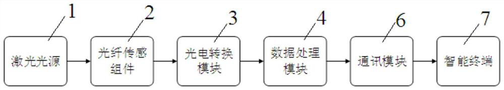
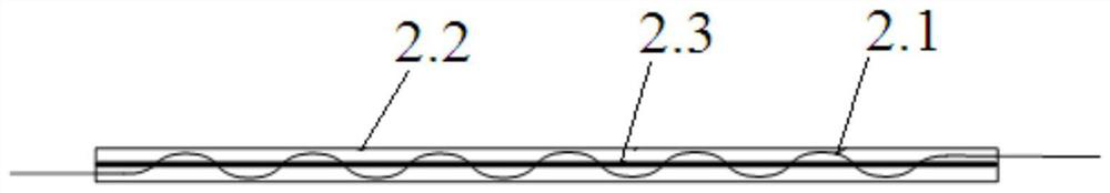
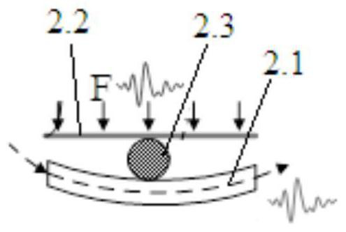
[0028] Such as figure 1 The shown pulse wave monitoring device based on optical fiber sensing includes a laser light source 1, a photoelectric conversion module 3, a data processing module 4 and a plurality of optical fiber sensing components 2 arranged in parallel (the more components, the larger the detection range , the pulse wave information that can be reflected is more abundant), wherein, each optical fiber sensing component 2 all comprises sensing optical fiber 2.1, vibration-sensitive film 2.2 and hard pressing line 2.3, and described hard pressing line 2.3 sticks Fixed on the vibration sensitive film 2.2 (the length direction of the hard crimping line 2.3 is the same as that of the vibration sensitive film 2.2), the sensing fiber 2.1 is wound on the vibration sensitive film 2.2, and the hard crimping line 2.3 is located on the sensing f...


PUM

PropertyMeasurementUnit
widthaaaaaaaaaa
diameteraaaaaaaaaa

Abstract

The invention discloses a pulse wave monitoring device based on optical fiber sensing. Its laser light source outputs laser signals to the sensing optical fibers of each optical fiber sensing component. The pressure change caused by the pulse wave produces a corresponding change in the bending radius of the optical fiber, and the laser signal transmitted in each sensing fiber is lost at the bending position and modulated based on the principle of bending loss; the data processing module extracts from the electrical signal representing the pulse wave The pulse wave signals of different positions of blood vessels corresponding to the physical positions of each sensing fiber are output, and the pulse wave is received by the distance between the hard pressure lines of adjacent fiber sensing components and the sensing fiber of adjacent fiber sensing components The time difference of the signals calculates the pulse wave velocity. The invention utilizes the characteristic that the optical fiber sensing component is sensitive to micro-vibration to measure the pulse vibration signals of different adjacent parts of the human body.

Description

technical field [0001] The invention relates to the technical field of monitoring human vital signs, in particular to a pulse wave monitoring device and method based on optical fiber sensing. Background technique [0002] Cardiovascular disease is one of the serious diseases that endanger human health, and the World Health Organization has listed it as the number one killer that endangers human health in the 21st century. A large number of studies have shown that in the early stages of hypertension and arteriosclerosis, although there are no obvious symptoms, a series of parameters reflecting cardiovascular conditions such as blood pressure, blood flow, vascular resistance, and vascular elasticity have actually begun to change. And firstly reflected in the change of pulse wave. Therefore, the quantification of pulse wave information has important reference value for cardiovascular diseases. If changes in these parameters can be detected in time and their characteristics an...

Claims


Application Information

Patent Timeline
Patent Type & Authority Patents(China)
IPC IPC(8): A61B5/024
CPCA61B5/02416A61B5/02427
Inventor 李政颖赵涛黄龙庭詹婧陈可为
Owner WUHAN UNIV OF TECH
Why Eureka
Try Eureka