A Measuring System for Large Aperture Optical Components Based on Ultrafast Laser Imaging

A technology of optical components and measurement systems, which is applied in the direction of optical instrument testing, measuring devices, and testing optical properties, etc., can solve problems such as large-scale and high-speed measurement of optical components, and achieve the effects of widening applications, high flatness, and flexible evaluation modes

Active Publication Date: 2021-08-06
INST OF APPLIED ELECTRONICS CHINA ACAD OF ENG PHYSICS
View PDF7 Cites 0 Cited by
  • Summary
  • Abstract
  • Description
  • Claims
  • Application Information

AI Technical Summary

Problems solved by technology

[0006] The purpose of the present invention is to provide a large-diameter optical element measurement system based on ultrafast laser imaging, in order to overcome the defects of the prior art and solve the problem that the prior art cannot achieve large-scale and high-speed measurement of optical elements. It can realize the surface measurement within the pulse time, and the measurement parameters include basic physical quantities such as the amplitude and phase of the optical element, which can realize real-time and online monitoring, and is helpful for in-depth analysis of the whole process state of the optical element.

Method used


Image

  • A Measuring System for Large Aperture Optical Components Based on Ultrafast Laser Imaging
  • A Measuring System for Large Aperture Optical Components Based on Ultrafast Laser Imaging

Examples


Embodiment 1

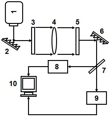
[0034] Such as figure 1 As shown in the figure, a transmission-type large-aperture optical element measurement system is shown in the figure.

[0035] The laser 1 generates ultrafast pulse laser under its normal operation, and the laser has the characteristics of wide spectrum, high coherence, high flatness, ultrafast pulse and so on.

[0036] The laser beam passes through the first diffraction grating 2 to undergo Fraunhofer diffraction, and the frequency domain (spectrum) information of the pulsed laser is mapped to the linear space domain in a one-to-one correspondence.

[0037] After passing through the first cylindrical prism or VIPAS, the line-like spot is converted into a rectangular spot through the method of cylindrical prism imaging or virtual imaging.

[0038] The light spot irradiates on the first optical element under test 4 , transmits through the first optical element under test 4 and carries its amplitude and phase information in real time.

[0039] The trans...

Embodiment 2

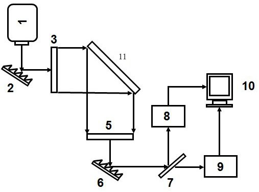
[0042] Such as figure 2 As shown in the figure, a reflective large-aperture optical element measurement system is shown in the figure.

[0043] The laser 1 generates ultrafast pulse laser under its normal operation, and the laser has the characteristics of wide spectrum, high coherence, high flatness, ultrafast pulse and so on.

[0044] The laser beam passes through the first diffraction grating 2 to undergo Fraunhofer diffraction, and the frequency domain (spectrum) information of the pulsed laser is mapped to the line-like space domain in a one-to-one correspondence.

[0045] After passing through the first light beam adjustment member 3, the line-like spot is converted into a rectangular spot by means of cylindrical prism imaging or virtual imaging.

[0046] The light spot is irradiated on the second optical element under test 11 , reflected on the second optical element under test 11 and carries its amplitude and phase information in real time.

[0047] The reflected li...

Embodiment 3

[0050] When conducting system verification experiments for specific optics. Attach the standard plate of standard size to the optical element to be tested. Through the final signal processing, it can be seen that the corresponding three occlusion lines have three obvious corresponding peaks in the signal, and the measured width is consistent with the actual width. The large-diameter optical element measurement system based on ultrafast laser imaging provided by the present invention can be applied to real-time monitoring of large-diameter optical elements in high-power laser devices and static measurement of quality evaluation of large-diameter optical elements.

[0051] The laser 1 in Embodiments 1, 2 and 3 of the present invention can be a laser with optical fiber output, or a laser with spatial light output, and its output laser features mainly broad spectrum, high coherence, and high spectral flatness. Through the diffraction grating and Infraunhofer far-field diffraction,...


PUM


Abstract

The invention discloses a large-diameter optical element measurement system based on ultrafast laser imaging, which comprises a laser, a diffraction grating, a beam adjustment element, an optical element to be measured, a beam splitter, a dispersion element, a time lens module, and a high-speed detection system. The invention utilizes lasers to generate wide spectrum, high coherence, high flatness, ultrafast pulsed lasers; the frequency domain (spectrum) information of the pulsed lasers is mapped one-to-one to the linear-like space domain through Fraunhofer diffraction ; Convert the line-like light spot into a rectangular light spot by the method of cylindrical prism imaging or virtual imaging to realize real-time measurement of large aperture; finally realize the real-time measurement of the laser carrying the amplitude and phase information of the element to be measured through Fourier dispersion and time lens mapping respectively. Measurement.

Description

technical field [0001] The invention belongs to the fields of high-energy laser, ultrafast laser and Fourier optics, and in particular relates to a large-diameter optical element measurement system based on ultrafast laser imaging. Background technique [0002] At present, the power and working time of lasers have been significantly improved, and at the same time, new breakthroughs have been made in the application of high-energy lasers. In most large-scale high-energy laser devices, multiple expensive large-aperture optical components are integrated in each optical assembly. High-power lasers will cause thermal effects and electro-optic effects on optical components, making the surface of components prone to laser damage. [0003] In order to ensure the safe operation of large-scale high-energy laser systems, it is necessary to detect and track the damage at the initial stage, and repair it in time before the damage size reaches the threshold. Therefore, it is necessary t...

Claims


Application Information

Patent Timeline
Patent Type & Authority Patents(China)
IPC IPC(8): G01M11/02
CPCG01M11/0207
Inventor 彭琛周文超魏继锋黄德权常艳蒋志雄何均章
Owner INST OF APPLIED ELECTRONICS CHINA ACAD OF ENG PHYSICS
Why Eureka
Try Eureka