
Method and device for recovering argon discharged in monocrystalline silicon preparation

The technology of a recovery device and a recovery method is applied in the field of argon gas discharge in the process of purifying and recovering single crystal silicon, which can solve the problems of high energy consumption, low recovery rate of argon gas, and inability to overcome the problem of nitrogen accumulation, and achieve low energy consumption, The effect of reducing energy consumption and gas consumption and shortening time

Active Publication Date: 2021-06-25
DALIAN INST OF CHEM PHYSICS CHINESE ACAD OF SCI +1
View PDF7 Cites 2 Cited by
  • Summary
  • Abstract
  • Description
  • Claims
  • Application Information

AI Technical Summary

Problems solved by technology

The chemical looping combustion technology does not require an additional oxygen removal process, and the process is simple, but it cannot overcome the problem of nitrogen accumulation in the long-term cycle process
At present, the argon recovery method and device disclosed in US2012 / 0308462A1 have the disadvantages of high energy consumption during equipment operation and low argon recovery rate.

Method used


Image

  • Method and device for recovering argon discharged in monocrystalline silicon preparation
  • Method and device for recovering argon discharged in monocrystalline silicon preparation
  • Method and device for recovering argon discharged in monocrystalline silicon preparation

Examples


Embodiment 1

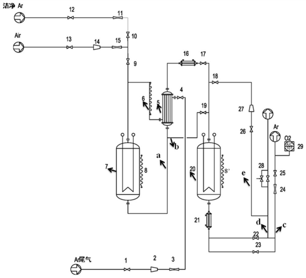
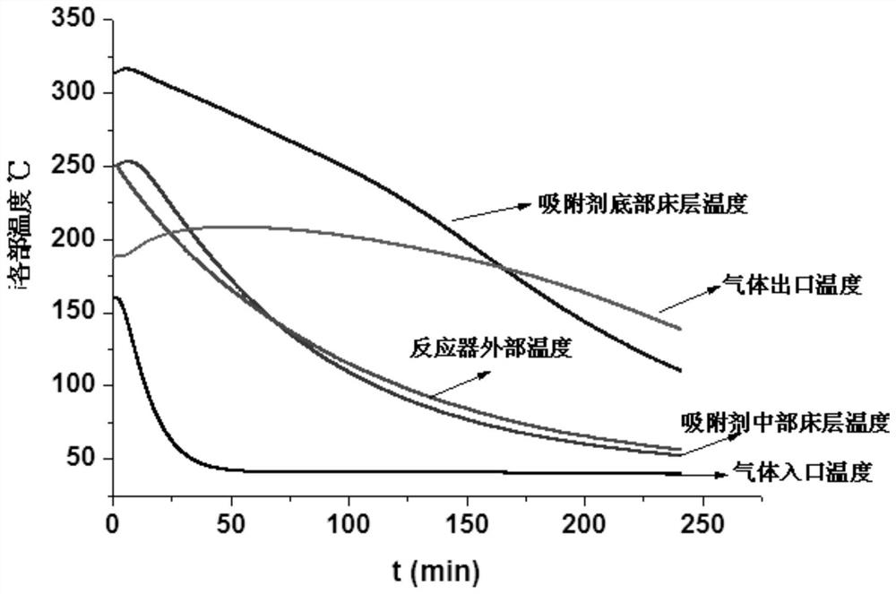
[0041] Embodiment 1, the pre-preparation process of the purification device: the temperature of the chemical looping combustion reactor (7) is raised to 270°C, the temperature of the adsorbent reactor (20) is raised to 250°C, the fifth valve (12) is opened, and the fourth valve (10) is , the third valve (9), the ninth valve (19), the eleventh valve (23), the twelfth valve (25), and all the other valves are closed. Adjust the argon gas flow meter from 11 to 10 L / min, keep it for 5 hours, and remove the impurities of oxygen carrier and adsorbent. Cooling process: open the tenth valve (22), the thirteenth valve (26), the eighth valve (18), and the rest of the valves are closed. Turn on the fan (27) and the second circulating water cooling device (21) to cool the adsorbent in the adsorbent reactor (20). For the specific cooling curve, refer to the attached figure 2 .

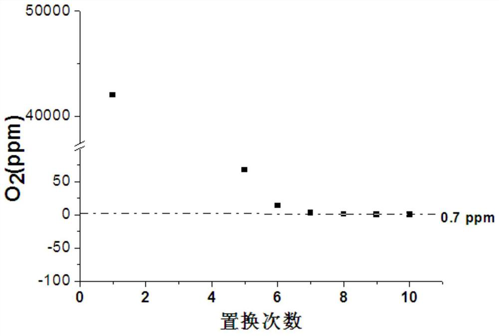
[0042] Replacement process, open the fifth valve (12), the fourth valve (10), the third valve (9), the second ...

Embodiment 2

[0044] Embodiment 2, regeneration process: open the fifth valve (12), the sixth valve (13), the fourth valve (10), the third valve (9), the ninth valve (19), the tenth valve (22), Fourteenth valve (28), all the other valves are closed. Adjust the second gas mass flow meter (11) to 50L / min. Adjust the third gas mass flow meter (15) to 10L / min, and open the air cooling dryer (14), the second circulating condensed water cooling device (21), and then the adsorbent reactor (20) is heated to 250 ° C, Keep for 2h. Then close the second gas mass flow meter (11), adjust the third gas mass flow meter (15) to 100L / min, keep it for another 2h, and end the regeneration process. The follow-up process repeats the cooling process and replacement process.

Embodiment 3

[0045] Example 3: The overall energy consumption monitoring of the reaction device after 152 hours of operation Refer to Table 1 for specific comparison results.

[0046] Table 1 Average energy consumption monitoring of purification equipment

[0047]

[0048] Explanation: The purification device has been running for 152 hours, and 10 switching operations have been carried out. It is detected that the average energy consumption during the operation of the device is about 4.5kW / h. Without purification device, about 547m of argon gas is needed 3 , and after using the purification device, only argon 47m 3 .


PUM


Abstract

The invention discloses a method for purifying and recovering argon tail gas discharged in a monocrystalline silicon preparation process. The method mainly comprises the following steps: 1) a purification process; 2) a regeneration process; 3) a cooling process; and 4) a replacement process. The invention further discloses a corresponding argon recovery device and a process thereof. The device comprises a chemical looping combustion reactor (7), a heat exchanger (5), an adsorbent reactor (20), circulating water cooling devices (16) and (21), a compressor (2), a circulating fan (27), an air freezing dryer (14), an oxygen analyzer (29), heat preservation sleeves (8) and (8'), an auxiliary heating device (6) and corresponding control valves. According to the invention, the device has the advantages of being simple in technological process, low in energy consumption and high in argon recovery rate at present.

Description

technical field [0001] The invention relates to a method and a device for discharging argon gas in a process for purifying and recovering single crystal silicon, and belongs to the technical field of purification and recovery of inert gases. Background technique [0002] With the increasing demand for renewable and clean energy, the photovoltaic power generation industry based on solar energy utilization has ushered in rapid development. The use of photovoltaic cells to generate electricity can provide the necessary power supply for homes, offices, etc. If it is further integrated into the power grid, it can provide industrial Production provides electrical support. At present, the large-scale application of photovoltaic cells is mainly silicon-based solar cell components. [0003] The main raw material for the process of producing silicon-based solar electronic components is crystalline silicon (single crystal silicon or polycrystalline silicon), and crystalline silicon is...

Claims


Application Information

Patent Timeline
IPC IPC(8): C01B23/00B01D53/62B01D53/46B01D53/72B01D53/02
CPCC01B23/00B01D53/62B01D53/46B01D53/72B01D53/02C01B2210/0034C01B2210/005C01B2210/0053C01B2210/007C01B2210/0015C01B2210/002B01D2259/4009B01D2257/504B01D2257/502B01D2257/108B01D2257/7025B01D2258/02Y02P20/151Y02A50/20Y02C20/20Y02C20/40
Inventor 李灿李军黎志欣逯占文朱剑王明升
Owner DALIAN INST OF CHEM PHYSICS CHINESE ACAD OF SCI
Learn More