
Directional heat-conducting fin and preparation method thereof, and semiconductor heat dissipation device

A technology of directional thermal conductivity and thermal conductivity filler, applied in the direction of semiconductor devices, semiconductor/solid-state device parts, electric solid-state devices, etc., can solve the problems of poor fluidity, difficult extrusion processing, uneven composition, etc. Has good orientation and orientation

Active Publication Date: 2021-07-23
GUANGDONG SUQUN NEW MATERIAL CO LTD
View PDF9 Cites 3 Cited by
  • Summary
  • Abstract
  • Description
  • Claims
  • Application Information

AI Technical Summary

Problems solved by technology

Baolima Technology Co., Ltd. published the patent CN100548099C, which uses a superconducting magnetic field and applies a certain frequency of vibration to make the carbon fiber with a high filling amount oriented along the direction of the magnetic field in the high-viscosity composition. Since the densities of the added alumina and carbon fiber fillers are respectively 3.8 times and 2 times the density of the silicone resin matrix, after the vibration is applied, it will cause the filler to settle, causing the overall composition to be uneven, and ultimately affect the uniformity of thermal conductivity
In addition, the high price and operating costs of superconducting magnets increase the cost
Dexerials Co., Ltd. announced CN107004651A, CN108463882A and CN109891577A. This method is to use the extrusion method to orient the carbon fiber along the extrusion method. We have found through our experiments that in order to prepare a high thermal conductivity sheet, when the mass ratio of the filled carbon fiber to the resin When it is greater than 1.3, the viscosity of the composition is large, the fluidity becomes poor, and it is difficult to extrude and process
In addition, when molding in a hollow mold, gaps are easily formed between adjacent extruded bodies due to poor fluidity, so the extrusion method is not suitable for the orientation of high-filling compositions
Published patent CN110734562A adopts annular groove to do circular motion, and the fiber in the composition in the groove is oriented along the direction of rotation, and there are following two disadvantages in this method: 1. the size of the obtained annular cured product is limited by the size of the annular groove, so , the width of the heat conduction sheet obtained by slicing the annular cured product along the radial direction is also limited by the width of the annular groove, and it is impossible to obtain a heat conduction sheet with a larger width; 2. When the width of the annular groove becomes larger, only the The composition on both sides of the tank wall is oriented, but the inside of the composition cannot receive the frictional force between the tank wall and the composition, which will cause insufficient orientation of the composition. This shortcoming is especially reflected in high-viscosity compositions, resulting in the inability to obtain High orientation, high thermal conductivity thermal conductive sheet

Method used


Image

  • Directional heat-conducting fin and preparation method thereof, and semiconductor heat dissipation device
  • Directional heat-conducting fin and preparation method thereof, and semiconductor heat dissipation device
  • Directional heat-conducting fin and preparation method thereof, and semiconductor heat dissipation device

Examples


Embodiment 1

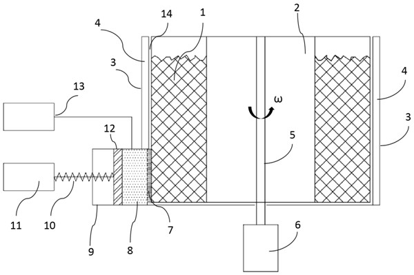
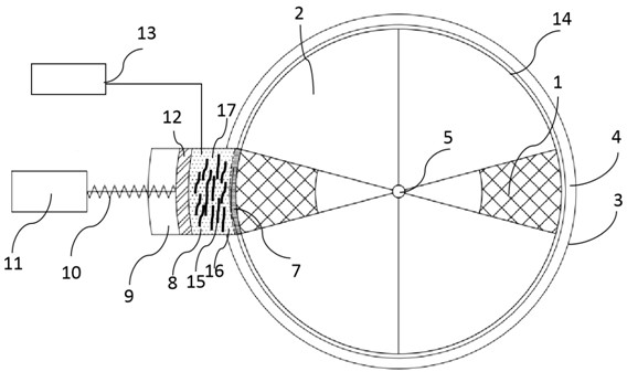
[0044] This embodiment provides an orientation forming device, see figure 1 and figure 2 , the orientation molding device includes:

[0045] Cylindrical drum 2, the central axis of the drum 2 is fixed with a rotating shaft 5, one end of the rotating shaft 5 is a motor one 6, and the motor one 6 drives the rotating drum 2 to rotate through the rotating shaft 5; Axisymmetric is the charging area 1, and the charging area 1 is two fan-shaped cylindrical areas, and the two fan-shaped cylindrical areas are arranged symmetrically with respect to the central axis of the drum. The bottom side of the drum 2 in the charging area 1 is provided with a drum opening;

[0046] A sleeve 3, the sleeve 3 is provided with an interlayer, and the interlayer is filled with a cooling medium 4. The sleeve 3 is sheathed outside the drum 2. In this embodiment, there is a gap 14 between the drum 2 and the sleeve 3, and the distance between the gaps 14 is 0.1-5mm. The drum 2 can rotate inside the sle...

Embodiment 2

[0052] This embodiment provides a method for preparing an oriented thermally conductive sheet, using an oriented forming device in Example 1, and the specific implementation steps are as follows:

[0053] S1. Ingredients: 100g of addition-type silicone oil (55g of vinyl silicone oil, 44.9g of hydrogen-containing silicone oil and 0.1g of platinum catalyst), 75g of carbon fiber powder (0.1mm in length, 15μm in diameter) and 300g of spherical alumina, mix and stir 30min, vacuum defoaming for 5min to form a fluid composition with a viscosity of 200,000 mPa·s;

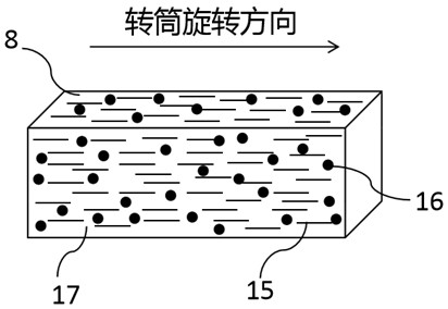
[0054] S2. Orientation molding: the fluid composition obtained in step S1 is placed in the symmetrical charging area of ​​the drum of the orientation molding device, and the angular velocity of the drum is set to 70r / min for circular motion. During the circular motion, the composition is subjected to the effect of centrifugal force Enter the gap between the drum and the sleeve from the opening at the bottom of the drum, the...

Embodiment 3

[0059] This embodiment provides a method for preparing an oriented thermally conductive sheet, using an oriented forming device in Example 1, and the specific implementation steps are as follows:

[0060] S1. Ingredients: 100g reactive silicone oil (a mixture of 55g vinyl silicone oil, 44.9g hydrogen-containing silicone oil and 0.1g platinum catalyst), 120g carbon fiber powder (0.1mm in length, 15μm in diameter), 300g spherical alumina and 50g spherical Aluminum nitride, mixed and stirred for 30 minutes, vacuum degassed for 5 minutes to form a fluid composition with a viscosity of 650,000 mPa s;

[0061] S2. Orientation molding: the fluid composition obtained in step S1 is placed in the symmetrical charging area of ​​the drum of the orientation molding device, and the angular velocity of the drum is set to 90r / min for circular motion. During the circular motion, the composition is subjected to the effect of centrifugal force Enter the gap between the drum and the sleeve from t...


PUM

PropertyMeasurementUnit
viscosityaaaaaaaaaa
thicknessaaaaaaaaaa

Abstract

The invention belongs to the field of heat-conducting fin preparation technologies and semiconductor heat dissipation, and particularly discloses a preparation method of a directional heat-conducting fin, which comprises the following steps: S1, preparing a fluid composition for the heat-conducting fin; S2, placing the fluid composition obtained in the step S1 in an orientation forming device, applying high-speed shearing force of circular motion to the fluid composition layer by layer, orienting the heat-conducting filler in the fluid composition in the shearing direction, forming oriented thin-layer compositions, collecting the thin-layer compositions in a mold layer by layer, forming a continuous multi-layer collection body, S3, carrying out thermocuring on the multi-layer convergence body to obtain an oriented composition block; and S4, slicing the oriented composition block along a direction vertical to the orientation to obtain the oriented heat-conducting sheet. The convergence body prepared by the method is good in orientation, few in defect and high in efficiency, the heat-conducting fin obtained by slicing treatment has high orientation, high heat conductivity and uniformity, and meanwhile, the heat-conducting fin can be well applied to a semiconductor heat dissipation device.

Description

technical field [0001] The invention relates to the preparation technology of a heat conduction sheet and the field of semiconductor heat dissipation, in particular to a preparation method of an oriented heat conduction sheet and a semiconductor heat dissipation device. Background technique [0002] With the development of 5G technology, the power density of chips continues to increase, which puts forward higher requirements for the heat dissipation of chips. In heat dissipation components, thermally conductive silicone gaskets are usually used to reduce the interface thermal resistance between the chip and the heat sink and improve heat dissipation efficiency. [0003] At present, conventional thermally conductive silica gel gaskets are realized by filling isotropic spherical thermally conductive fillers (aluminum oxide, aluminum nitride, zinc oxide, etc.) in the silica gel matrix. Due to the low intrinsic thermal conductivity of spherical ceramic fillers, the gasket It is...

Claims


Application Information

Patent Timeline
Patent Type & Authority Applications(China)
IPC IPC(8): C08L83/07C08L83/05C08K7/06C08K7/18C08J5/18C08J3/00H01L23/367
CPCC08J5/18C08J3/00H01L23/3672C08J2383/07C08J2483/05C08K7/06C08K7/18
Inventor 任泽明王号
Owner GUANGDONG SUQUN NEW MATERIAL CO LTD
Learn More