Underground coal mine deep hole compound type diameter expanding cave making device
A composite, deep-hole technology, applied in drilling equipment, drilling equipment and methods, drilling with liquid/gas jets, etc., can solve problems such as uneven hole size, inability to transmit power, complex transmission structure, etc., to achieve transmission The effect of direct and fast efficiency, stable gear transmission structure, and simplified transmission components
- Summary
- Abstract
- Description
- Claims
- Application Information
AI Technical Summary
Problems solved by technology
Method used
Image


Examples
Embodiment 1
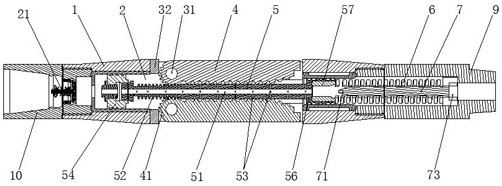
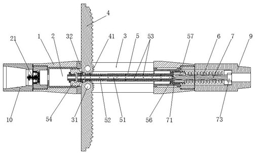
[0045] Such as Figure 1-3 As shown, a coal mine underground deep hole compound diameter expanding hole making device is arranged between the drill pipe and the drill bit, and includes a rod body 1 with a central through hole 2, and the head end and tail end of the rod body 1 are respectively provided with male The head 9 and the female head 10, the male head 9 is used to connect the drill bit, the female head 10 is used to connect with the drill pipe, a plurality of assembly holes 3 connected with the central through hole 2 are evenly opened on the circumferential wall of the rod body 1, and the assembly The hole 3 is arranged along the length direction of the rod body 1, and the assembly hole 3 is a through hole with a rectangular structure. The diameter-expanding drill wing 4 that can be flipped and opened relative to the rod body is provided in the assembly hole 3, and the shape of the expanded-diameter drill wing 4 is The diameter and size match the shape and size of the ...
Embodiment 2
[0050] This embodiment is an improvement made on the basis of Embodiment 1, and its main structure is the same as that of Embodiment 1, the difference is that: Figure 6 As shown, the expanded diameter drill wing 4 includes three parts integrally connected, which are respectively a cylindrical end 42 for connection, a rectangular wing bar 43 as the main body, and a trapezoidal cutting seat 44 for cutting. The expanded diameter drill wing 4 works In this state, the coal seam wall needs to be cut, and at the same time, it needs to bear the high torque caused by the high-speed rotation of the drill pipe and the cutting of the coal seam wall. As a basic guarantee, the rotating teeth 41 are evenly arranged on the circumferential wall of the cylindrical end 42. At the same time, the cylindrical end 42 as the connecting end also needs sufficient connection strength, so the main structure of the cylinder is adopted. The center of the cylindrical end 42 is provided with a pin shaft 31 ...
Embodiment 3
[0052] This embodiment is an improvement made on the basis of Embodiment 2, and its main structure is the same as that of Embodiment 2, the difference is that the thickness of the trapezoidal cutting seat 44 is smaller than the thickness of the rectangular wing bar 43, so that the trapezoidal cutting seat 44 and A step-shaped notch A47 is formed before the rectangular wing bar 43, and the notch A47 is positioned at the back side of the cutting alloy block 46, and the trapezoidal cutting seat 44 is positioned at the end of the same side of the cutting alloy block 46 to provide a step-shaped notch B48, the notch A47 and Alloy cutter 49 that fits in shape is assembled in the gap B48, on the two sidewalls of trapezoidal cutting seat 44, except wherein one sidewall has assembled cutting alloy block 46, also assembles a whole on the other sidewall The block alloy cutter 49 makes the both side walls of the trapezoidal cutting seat 44 have cutting ability, which can cooperate with the ...
PUM
 Abstract
Description
Claims
Application Information
 - R&D
- Intellectual Property
- Life Sciences
- Materials
- Tech Scout
- Unparalleled Data Quality
- Higher Quality Content
- 60% Fewer Hallucinations
Browse by: Latest US Patents, China's latest patents, Technical Efficacy Thesaurus, Application Domain, Technology Topic, Popular Technical Reports.
© 2025 PatSnap. All rights reserved.Legal|Privacy policy|Modern Slavery Act Transparency Statement|Sitemap|About US| Contact US: help@patsnap.com