High-temperature steel slag waste heat recovery device

A technology of waste heat recovery device and steel slag, which is applied in the direction of steam engine device, waste heat treatment, energy efficiency improvement, etc., can solve the problems of lack of humanity, low effective utilization of resources, and less use of waste heat, etc., and achieve high resource utilization rate and waste heat utilization High, the effect of improving the utilization rate

Active Publication Date: 2021-11-12
江西联达冶金有限公司
View PDF5 Cites 0 Cited by
  • Summary
  • Abstract
  • Description
  • Claims
  • Application Information

AI Technical Summary

Problems solved by technology

[0003] In the actual use process, due to the accumulation of steel slag in the process of waste heat utilization of the existing high-temperature steel slag waste heat recovery device, it is easy to cause the heat of the steel slag in the inner layer to be unable to be well utilized, resulting in a poor waste heat recovery effect, and the existing Most of the waste heat is returned to the interior of the device. The use of waste heat is relatively small, and the effective utilization of resources is relatively low. It is not humanized enough and has certain limitations.

Method used


Image

  • High-temperature steel slag waste heat recovery device
  • High-temperature steel slag waste heat recovery device
  • High-temperature steel slag waste heat recovery device

Examples


Embodiment 1

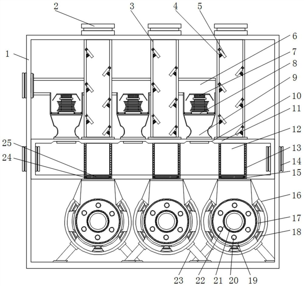
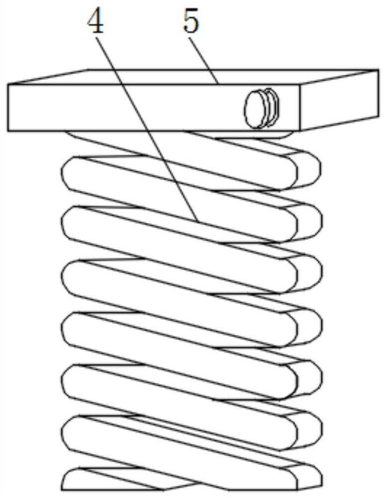
[0036] Embodiment one, with reference to Figure 1-8 , a high-temperature steel slag waste heat recovery device, including a fuselage body 1 and support legs 23, a water tank 11 is fixedly installed in the middle of the fuselage body 1, and several groups of feeding pipes 3 are evenly installed on the top surface of the water tank 11, and the inside of the feeding pipe 3 Several groups of baffle plates 5 are installed on the surface positions of both sides evenly through the rotating shaft, and the middle position of the bottom surface of the baffle plate 5 is fixed with a telescopic spring 4 . Several groups of Laval nozzles 9 are evenly installed between the top surface position and the feeding pipeline 3, and the top surface position of the Laval nozzles 9 is connected with a steam pipeline 6, and a steam turbine 8 is arranged inside the steam pipeline 6, and the top surface position of the steam turbine 8 is A generator 7 is connected, and a sealing mechanism 15 is located...

Embodiment 2

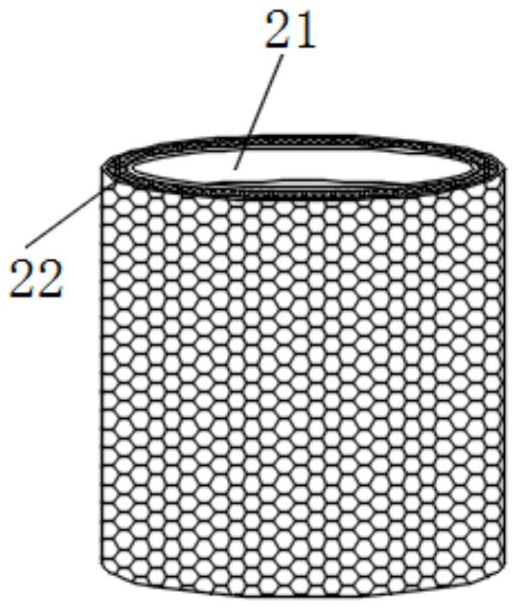
[0037] Embodiment two, refer to figure 1 , image 3 , Figure 4 , Figure 5 and Figure 8 , the position of the bottom surface of the water tank 11 is connected with an arc-shaped groove 16, and several groups of air-jet pipes 18 are evenly installed on the surface of the arc-shaped groove 16. Turntable 19, electric turntable 19 side surface positions are evenly equipped with several component rods 20, electric turntable 19 one side surface middle position is clamped with air outlet pipe 21, air outlet pipe 21 outer periphery is wrapped with filter screen 22, through filter screen 22 can The steel slag is isolated to prevent the steel slag from being discharged through the air outlet pipe 21.

Embodiment 3

[0038] Embodiment three, refer to figure 1 The heat radiation plate 13 is arranged symmetrically in the middle of both sides of the waste heat mechanism 12. The heat generated by the high temperature steel slag can be better absorbed through the heat radiation plate 13, and the effect of waste heat recovery is improved.


PUM


Abstract

The invention discloses a high-temperature steel slag waste heat recovery device. The high-temperature steel slag waste heat recovery device comprises a machine body and supporting legs, wherein a water tank is fixedly installed in the middle of the interior of the machine body, a plurality of sets of discharging pipelines are evenly installed on the surface of the top of the water tank, and a plurality of sets of material baffles are evenly installed on the surfaces of the two sides of the interior of each discharging pipeline in a crossed mode through rotating shafts. According to the high-temperature steel slag waste heat recovery device, Laval spray pipes, steam turbines and generators are adopted, in the using process, high-temperature steel slag falls into waste heat mechanisms, then heat is transmitted to heat radiation plates to heat water in the water tank, water steam is generated, and the generated water steam can only move upwards to be discharged out of the device due to sealing of the device; and in the steam moving process, the speed of steam can be increased through the Laval spray pipes, the steam turbines can be impacted at a higher speed so that the steam turbines can drive the generators to operate, the purpose of steam power generation is achieved, the utilization rate of resources is increased, and the device has the advantage of being high in resource utilization rate.

Description

technical field [0001] The invention relates to the technical field of waste heat recovery, in particular to a high-temperature steel slag waste heat recovery device. Background technique [0002] Steel slag is a kind of industrial solid waste, which is the slag discharged from steelmaking. It is divided into converter slag, open hearth furnace slag and electric furnace slag according to the furnace type. It is mainly composed of calcium, iron, silicon, magnesium and a small amount of oxides such as aluminum, manganese and phosphorus. . [0003] In the actual use process, due to the accumulation of steel slag in the process of waste heat utilization of the existing high-temperature steel slag waste heat recovery device, it is easy to cause the heat of the steel slag in the inner layer to be unable to be well utilized, resulting in a poor waste heat recovery effect, and the existing Most of the waste heat is returned to the interior of the device. The use of waste heat is re...

Claims


Application Information

Patent Timeline
Patent Type & Authority Applications(China)
IPC IPC(8): F01K11/02F01K17/00F01K17/02F01D9/06F01D15/10C21B3/08F27D17/00F22B1/04
CPCF01K11/02F01K17/00F01K17/02F01D9/06F01D15/10C21B3/08F27D17/004F22B1/04C21B2400/08Y02P10/20Y02P10/25
Inventor 彭志龙彭军昌潘理华李伟李忠于邓斌黄联斌
Owner 江西联达冶金有限公司
Why Eureka
Try Eureka