Broadband low-noise amplifier with reconfigurable frequency band

A broadband low-noise, amplifier technology, applied in low-noise amplifiers, amplifiers, amplifier combinations, etc., can solve the problems of difficulty in meeting noise and gain, large chip area, large circuit size, etc., to achieve good practical value, increase gain, reduce The effect of small gain fluctuations

Active Publication Date: 2021-11-19
UNIV OF ELECTRONICS SCI & TECH OF CHINA
View PDF10 Cites 1 Cited by
  • Summary
  • Abstract
  • Description
  • Claims
  • Application Information

AI Technical Summary

Problems solved by technology

Although balanced amplifiers can work in the best noise or maximum gain state, there are problems of large circuit size and high power consumption due to the need for two hybrid networks and two separate amplifiers; the bandwidth of a distributed amplifier is very wide, theoretically The cut-off frequency of the transistor can be achieved on the above, but due to the use of multiple spiral inductors or transmission lines, the chip area is large and the power consumption is high; the parallel-series feedback structure can provide good broadband matching and gain over the entire broadband, but it is difficult Satisfy the balance between noise and gain

Method used


Image

  • Broadband low-noise amplifier with reconfigurable frequency band
  • Broadband low-noise amplifier with reconfigurable frequency band
  • Broadband low-noise amplifier with reconfigurable frequency band

Examples


Embodiment 1

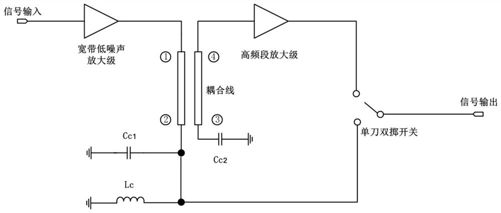
[0030] A broadband low-noise amplifier with reconfigurable frequency band, its architecture diagram is as follows figure 1 As shown, it includes a broadband low-noise amplifier stage, a coupling line, a through-end termination inductor, a direct-end termination capacitor, an isolation end termination capacitor, a high-frequency band amplifier stage, and a single-pole double-throw switch; the output of the broadband low-noise amplifier stage connected to the input terminal 1 of the coupled line, the straight-through end 2 of the coupled line is connected to the first rotating end of the SPDT switch, one end of the straight-through end connected to the inductor Lc, and one end of the straight-through end connected to the capacitor Cc1, the coupling of the coupled line Terminal 4 is connected to the input terminal of the high-frequency amplifier, the output terminal of the high-frequency amplifier is connected to the second rotating terminal of the SPDT switch, the isolated termin...

Embodiment 2

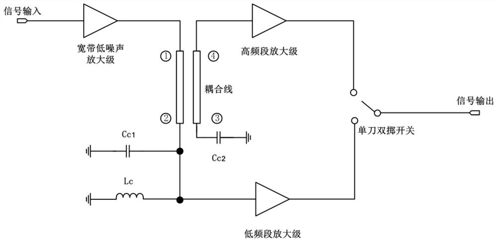
[0054] If the signal is amplified by a broadband low-noise amplifier stage and then the gain of the low-frequency signal coming through the straight-through end of the coupling line is smaller than that of the high-frequency signal, a low-frequency band can be added between the SPDT switch and the coupling line structure Amplifying stage to reduce gain fluctuation, the schematic diagram of the architecture is shown in image 3 shown.

[0055] The straight-through end of the coupling line inputs the low-frequency signal to the low-frequency amplifier stage. The circuit structure of the low-frequency amplifier stage can be the same as that of the high-frequency amplifier stage. The high-band signal is selected for output through a single-pole double-throw switch.

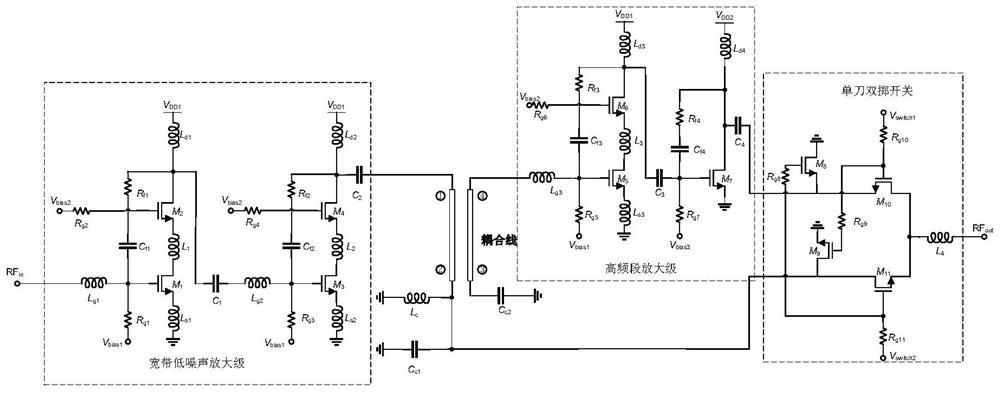
[0056] Figure 4 and Figure 5 For embodiment 1 of the present invention figure 2 The circuit structure shown is based on the reconstruction noise diagram and reconstruction gain performance diagram realized by G...


PUM


Abstract

The invention provides a broadband low-noise amplifier with a reconfigurable frequency band, and belongs to the technical field of radio frequency integrated circuits. According to the amplifier, a broadband signal is divided into two frequency band signals through a coupling line structure, so that a circuit can be optimally designed according to the noise, gain and other performance of each section of signal, frequency reconfiguration is achieved through switching of the single-pole double-throw switch, and the amplifier has the advantages of being low in noise, high in gain and reconfigurable in broadband. Meanwhile, the flexibility of circuit design is improved, miniaturization and integration of a communication system are better facilitated, implementation is easy, and good practical value is achieved.

Description

technical field [0001] The invention belongs to the technical field of radio frequency integrated circuits, and in particular relates to a broadband low-noise amplifier with reconfigurable frequency bands. Background technique [0002] Nowadays, with the rapid development of wireless communication technology, industries such as mobile phones, wireless local area networks, Internet of Things, and digital high-definition televisions have brought about tremendous changes in people's daily lives, and at the same time, they have also put forward higher requirements for RF chip design technology. The functional integration of many application devices is getting higher and higher, and a certain system often integrates multiple functional subsystems. Taking civilian mobile phones as an example, it also integrates functions such as GSM, W-CDMA, 5G, WIFI, Bluetooth and navigation. Each sub-functional system of the receiver front end of traditional multi-functional integrated equipmen...

Claims


Application Information

Patent Timeline
Patent Type & Authority Applications(China)
IPC IPC(8): H03F3/68H03F1/26H03F1/42
CPCH03F3/68H03F1/26H03F1/42H03F2200/294H03F2200/372Y02D30/70
Inventor 王勇陈满健王振宇杨涛
Owner UNIV OF ELECTRONICS SCI & TECH OF CHINA
Why Eureka
Try Eureka