Oil-rich coal in-situ pyrolysis and carbon capture coupling system

An in-situ pyrolysis and carbon capture technology, applied in coal gasification, lighting and heating equipment, indirect carbon dioxide emission reduction, etc., can solve pollution, surface soil pollution and other problems, to reduce pollution, increase oil yield, reduce The effect of energy input

Active Publication Date: 2021-12-03
XI AN JIAOTONG UNIV
View PDF26 Cites 4 Cited by
  • Summary
  • Abstract
  • Description
  • Claims
  • Application Information

AI Technical Summary

Problems solved by technology

The process of conventional mining to the ground and then refining oil in the refining furnace produces a lot of pollution, and the pyrolysis residue with low volatile content after pyrolysis is also a huge amount of solid waste. produce pollution

Method used


Image

  • Oil-rich coal in-situ pyrolysis and carbon capture coupling system

Examples


Embodiment Construction

[0028] The present invention is described in further detail below in conjunction with accompanying drawing:

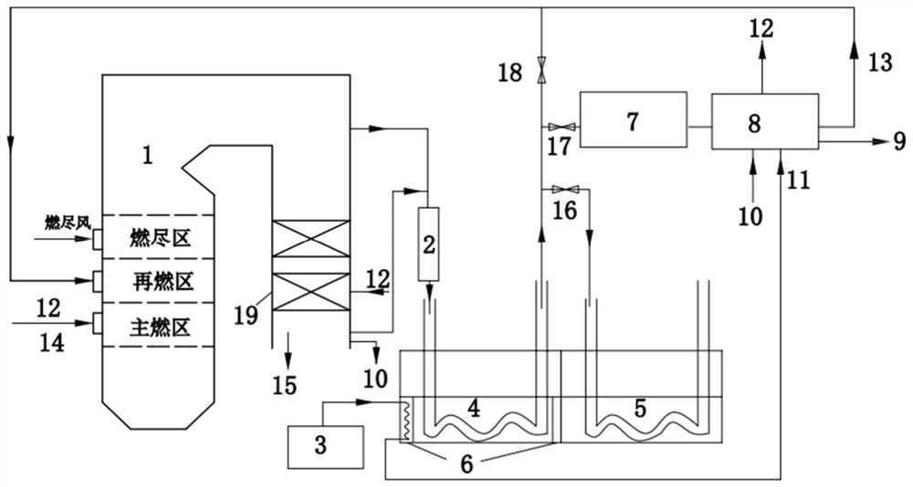
[0029] see figure 1 , a system for in-situ pyrolysis of oil-rich coal coupled with carbon capture provided by the present invention, comprising a power plant oxygen-rich combustion boiler 1, a compressor 2, an air separation device 3, a first coal seam block 4, a second coal seam Block 5, freeze wall 6, in-situ coal pyrolysis part composed of fuel 14; heat exchanger for heating feed water 7, gas-liquid separation device 8, oil product 9, circulating carbon dioxide 10, pure oxygen 11, primary air 12, organic Gas 13, fuel 14, captured carbon dioxide 15, first valve 16, second valve 17, third valve 18, waste heat utilization part of boiler air preheater 19. The system comprehensively considers the optimization of in-situ pyrolysis part, waste heat utilization part and carbon capture, and develops the process of flue gas pyrolysis of coal seam, comprehensive utilization o...


PUM


Abstract

The invention discloses an oil-rich coal in-situ pyrolysis and carbon capture coupling system. The oil-rich coal in-situ pyrolysis and carbon capture coupling system comprises a power station oxygen-rich combustion boiler, a compressor, an air separation device, a heat exchanger, a gas-liquid separation device and a boiler air preheater. In order to solve the problem that fuel with high tar yield such as oil-rich coal is easy to decompose to generate oil gas after being heated, flue gas at the tail of an oxygen-enriched combustion power station boiler is adopted to heat an underground coal seam, so that in-situ pyrolysis oil extraction of coal is realized, and gradient utilization of energy in the in-situ coal pyrolysis process is completed. Oil generated in the pyrolysis process is extracted, other substances are fully utilized, and carbon dioxide is captured. The process of inputting the fuel and outputting electric energy and the oil in the whole system is achieved, and pollutants and the carbon dioxide are not discharged. According to the oil-rich coal in-situ pyrolysis and carbon capture coupling system, in the in-situ pyrolysis process, clean and efficient utilization of the oil-rich coal is achieved, and the goal of energy carbon neutralization is promoted.

Description

technical field [0001] The invention relates to a system for coupling oil-rich coal in-situ pyrolysis and carbon capture. Background technique [0002] The development of unconventional oil and gas resources provides another route to the supply of oil, and its thermal pyrolysis can produce a considerable amount of oil and gas products. Pyrolysis conversion of these coals can avoid direct burning of coals, reduce air pollution, and enhance national energy security. The process of conventional mining to the ground and then refining oil in the refining furnace produces a lot of pollution, and the pyrolysis residue with low volatile content after pyrolysis is also a huge amount of solid waste. produce pollution. Underground in-situ pyrolysis, as an emerging mode, can reduce pollution to the atmosphere and soil. The heating and pyrolysis extraction process is carried out underground, but since the pyrolysis process requires a large amount of thermal energy to heat the formation...

Claims


Application Information

Patent Timeline
Patent Type & Authority Applications(China)
IPC IPC(8): E21B43/243E21B43/295F22B33/18F23L7/00F23L15/00
CPCE21B43/243E21B43/295F22B33/18F23L7/007F23L15/00Y02P90/70
Inventor 王长安毛崎森周磊赵林车得福
Owner XI AN JIAOTONG UNIV
Why Eureka
Try Eureka