High-strength steel thick plate narrow gap welding method and system based on paraxial laser-coaxial wire feeding-electromagnetic field synergy

A technology of coaxial wire feeding and welding method, used in laser welding equipment, welding equipment, metal processing equipment, etc., can solve the problems of molten pool crystallization crack, embrittlement and softening, large heat input, etc., to avoid uneven structure , the effect of suppressing crystallization cracks in welds, improving the stability of optical filament coupling and welding efficiency

Pending Publication Date: 2021-12-31
CHANGSHA UNIVERSITY OF SCIENCE AND TECHNOLOGY
View PDF1 Cites 0 Cited by
  • Summary
  • Abstract
  • Description
  • Claims
  • Application Information

AI Technical Summary

Problems solved by technology

[0005] The purpose of the present invention is to solve the problem of embrittlement and softening due to large heat input during narrow gap laser welding of high-strength steel thick plates used in engineering machinery, resulting in coarse structure in the heat-affected zone, and crystal cracks caused by uneven solidification of the molten pool. Axial laser-coaxial wire feeding-electromagnetic field synergistic high-strength steel thick plate narrow gap welding method and system

Method used


Image

  • High-strength steel thick plate narrow gap welding method and system based on paraxial laser-coaxial wire feeding-electromagnetic field synergy
  • High-strength steel thick plate narrow gap welding method and system based on paraxial laser-coaxial wire feeding-electromagnetic field synergy
  • High-strength steel thick plate narrow gap welding method and system based on paraxial laser-coaxial wire feeding-electromagnetic field synergy

Examples


Embodiment Construction

[0042] The following will be combined with Figure 1-4 The technical solution of the present invention will be described in detail along with specific embodiments.

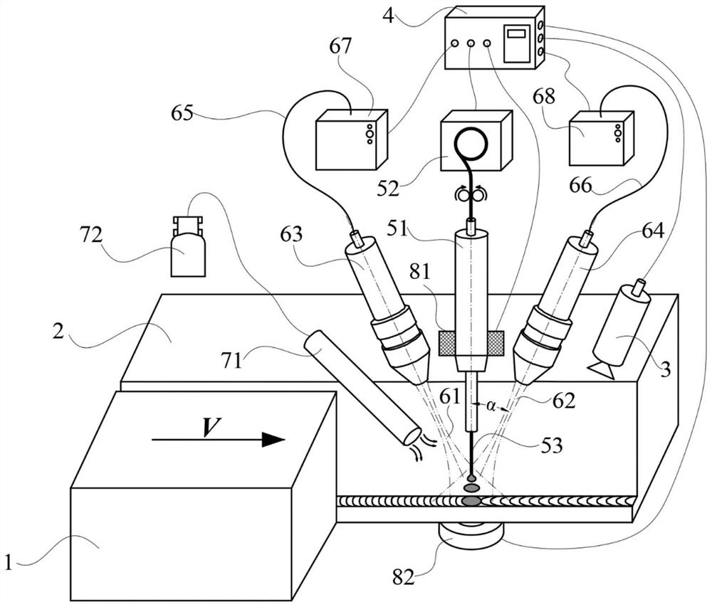
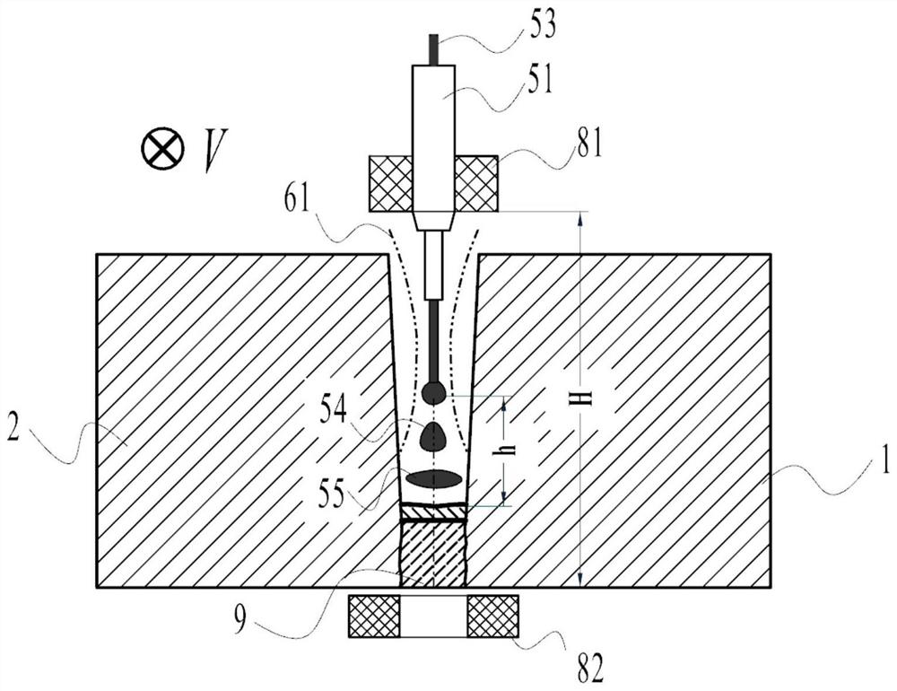
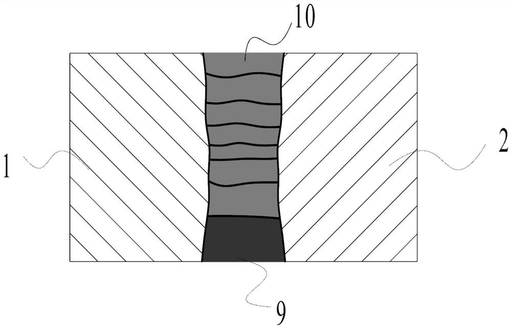
[0043] like Figure 1-4 As shown, the embodiment of the present invention provides a high-strength steel thick plate narrow-gap welding method based on paraxial laser-coaxial wire feeding-electromagnetic field cooperation, including the following steps:

[0044] Step 1: Provide a 30mm thick first base metal 1 and a 30mm thick second base metal 2. The width of the upper end of the bevel is 5mm, and the width of the lower end is 3mm, and they are butted to form a narrow gap joint, and the narrow gap is completed by laser self-fusion welding. The backing welding of the gap joints is used to obtain the backing weld 9.

[0045] Step 2: Provide laser wire-filling welding system, which includes: coaxial wire feeding system 5, side-axis double-beam laser system 6, electromagnetic field system 8, side-axis shielding gas ...


PUM

PropertyMeasurementUnit
diameteraaaaaaaaaa
magnetic flux densityaaaaaaaaaa

Abstract

The invention discloses a high-strength steel thick plate narrow gap welding method based on paraxial laser-coaxial wire feeding-electromagnetic field synergy. The method mainly comprises the following steps of providing a first base material and a second base material, carrying out butting to form a narrow gap joint, and finishing backing welding by adopting laser self-fusion welding; providing a laser wire filling welding system; starting the laser wire filling welding system, a weld joint surface contour detector, a first laser head, a coaxial wire feeding head, a second laser head, a first electromagnetic coil, a second electromagnetic coil and a paraxial nozzle moving synchronously, and carrying out welding. The invention further discloses a high-strength steel thick plate narrow gap welding system based on the paraxial laser-coaxial wire feeding-electromagnetic field synergy. According to the high-strength steel thick plate narrow gap welding method and system based on the paraxial laser-coaxial wire feeding-electromagnetic field synergy, the problems of large heat-affected zone structure and cracks caused by large welding heat input in an existing high-strength steel thick plate narrow gap laser welding process are solved, and the outstanding advantages of being good in process stability, high in welding efficiency and the like are achieved.

Description

technical field [0001] The invention relates to the field of laser welding, in particular to a narrow-gap welding method and system for high-strength steel thick plates based on the synergy of paraxial laser-coaxial wire feeding-electromagnetic field. [0002] technical background [0003] With the development of modern construction machinery towards large-scale and high-load capacity, the application of high-strength steel thick plate welding is becoming more and more extensive. Thick plate narrow-gap laser wire-filled welding method is a high-efficiency and high-quality welding technology, which takes into account the advantages of narrow-gap welding and laser welding. Disadvantages such as large thermal damage, coarse weld grains, and low welding efficiency. However, when this method is used to weld thick plates, due to the small groove width, when the filling amount is large, the molten metal in the single-layer weld is large in the depth direction, and the depth-to-widt...

Claims


Application Information

Patent Timeline
Patent Type & Authority Applications(China)
IPC IPC(8): B23K26/211B23K26/044B23K26/12B23K26/70
CPCB23K26/211B23K26/044B23K26/702B23K26/123
Inventor 张明军黄钰彬毛聪管付如龚俊李康为宋祖源曾勇唐昆唐伟东罗源嫱胡永乐
Owner CHANGSHA UNIVERSITY OF SCIENCE AND TECHNOLOGY
Why Eureka
Try Eureka