
Hydrate accelerant and method for continuously separating and capturing CO2

A hydrate accelerator, CO2 technology, applied in separation methods, dispersed particle separation, chemical instruments and methods, etc., can solve the problems of low growth rate, long nucleation time, energy consumption and high cost of separation and capture technology, and achieve The effect of accelerating diffusion rate, less dosage, and promoting rapid nucleation and growth

Active Publication Date: 2022-01-07
SOUTHWEST PETROLEUM UNIV
View PDF8 Cites 0 Cited by
  • Summary
  • Abstract
  • Description
  • Claims
  • Application Information

AI Technical Summary

Problems solved by technology

[0007] The technical problem to be solved by the present invention is that the existing CO 2 Separation and capture technology consumes a lot of energy and costs, while hydrate separation of CO 2 There are disadvantages of long nucleation time and low growth rate, and the purpose is to provide a continuous separation and capture of CO 2 Hydrate promoter and method, first concentrate the CO in the mixed gas through membrane separation 2 Concentration, and then use the iron-based ionic liquid promoter to increase the CO 2 The formation rate of hydrate can not only reduce the preparation cost of membrane separation technology, improve the life of membrane reuse, but also make up for the limitation of the hydrate method for one-step separation of mixed gases

Method used


Image

  • Hydrate accelerant and method for continuously separating and capturing CO2
  • Hydrate accelerant and method for continuously separating and capturing CO2
  • Hydrate accelerant and method for continuously separating and capturing CO2

Examples


Embodiment 1

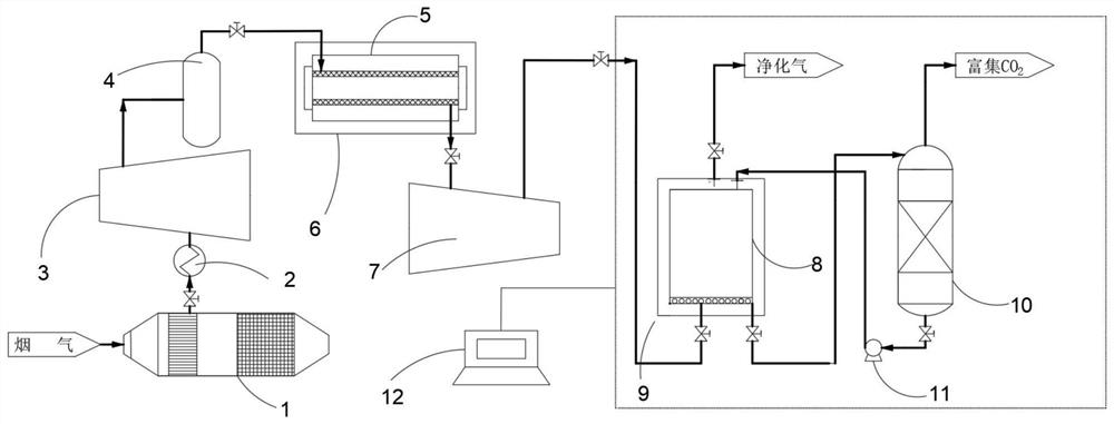
[0035] like figure 1 As shown, the embodiment of the present invention provides a CO 2 The method for separating and trapping comprises the steps of:

[0036] 1) CO 2 The mixed gas with a content of 5-10mol% is passed into the dust collector 1, and the large and fine particles of dust are filtered out. After the dust is removed, the mixed gas is cooled to 35°C by the condenser 2 and boosted to 0.5 by the gas booster pump-3. MPa, and stored in the gas storage tank 4;

[0037] 2) The dust-removing mixed gas is preliminarily separated through the Pebax composite membrane separator 5, and the internal temperature of the membrane separator is stabilized at 15-35°C with the constant temperature tank 16, so that the CO in the mixed gas 2 Concentration reaches more than 50mol%, and then use liquid delivery pump 11 to continuously input the ionic liquid aqueous solution containing 1-butyl-3-methylimidazolium ferric tetrachloride into the bubbling hydration autoclave 8, so that the s...

Embodiment 2

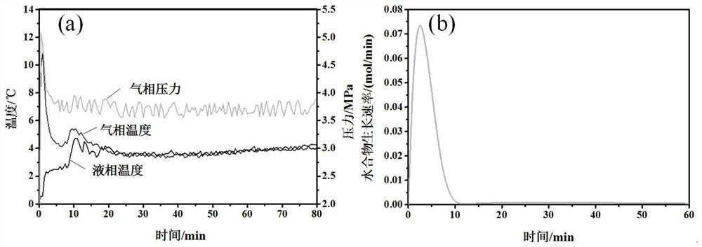
[0043] The difference between this embodiment 2 and embodiment 1 is that the CO 2 The hydration accelerator selects 25g / L 1-octyl-3-methylimidazolium ferric tetrachloride, such as image 3 (a), in CO 2 The rapid increase in liquid phase temperature during hydrate nucleation causes an increase in gas phase temperature, suggesting that CO 2 The nucleation of hydrates mainly occurs in the main body of the solution, such as image 3 As shown in (b), after hydrate nucleation, CO 2 The hydrate growth rate increased rapidly at first, reached the maximum within 5 minutes, and then gradually decreased.

[0044] In this example, CO 2 The induction time of hydrate nucleation is 7.8min, which is 56.7% lower than that of the pure water system, and the gas storage capacity reaches 110.4V / V, which is 10.1% higher than that of the pure water system.


PUM


Abstract

The invention discloses a hydrate accelerant and method for continuously separating and trapping CO2. The accelerant comprises alkyl imidazole ferric chloride and / or a derivative of the alkyl imidazole ferric chloride. The CO2 trapping method comprises the following steps: firstly introducing CO2-containing gas into a membrane separator for preliminary separation, and then conducting reaction in a hydrate accelerant aqueous solution. According to the invention, iron-based ionic liquid is used as an accelerant, and the aggregation of molecules of the iron-based ionic liquid and iron-based anions of the iron-based ionic liquid have relatively large free volumes, so that a mass transfer channel can be formed, the diffusion rate of H2O molecules and CO2 molecules can be accelerated, and rapid nucleation and growth of CO2 hydrate can be promoted. According to the CO2 trapping method disclosed by the invention, the concentration of CO2 in the mixed gas is increased through membrane separation, and the generation rate of CO2 hydrate is increased by utilizing the accelerant, so that the preparation cost of a membrane separation technology can be reduced, the service life of a membrane in repeated use is prolonged, and meanwhile, the limitation of one-step separation of the mixed gas by a hydrate method is made up.

Description

technical field [0001] The invention relates to the technical field of gas separation, in particular to a continuous separation and capture of CO 2 Hydrate promoter and method. Background technique [0002] With the development of human society and industry, the greenhouse gas CO 2 Emissions reached 14000MtCO 2 / year, making atmospheric CO 2 The concentration is increasing year by year, and has increased to 413.8ppm by 2021. The large amount of flue gas emissions from power plants is the main contributor to the increase in greenhouse gases, causing a series of climate and environmental problems, such as global warming, melting glaciers, and rising sea levels. Therefore, the flue gas is separated and the CO 2 Capture, storage, and resource utilization to reduce emissions have become particularly urgent. [0003] Traditional flue gas capture and separation technologies include physical absorption, chemical absorption, adsorption, membrane separation, cryogenic distillati...

Claims


Application Information

Patent Timeline
Patent Type & Authority Applications(China)
IPC IPC(8): B01D53/74B01D53/22B01D53/62B01D53/73
CPCB01D53/229B01D53/62B01D53/73B01D53/74B01D2257/504Y02A50/20Y02C20/40
Inventor 李爱蓉刘发平罗泽东
Owner SOUTHWEST PETROLEUM UNIV
Learn More