Device and method for reducing urea crystals of SCR system

A technology of SCR system and urea, which is applied to the electric control of exhaust device, muffler device, exhaust treatment device, etc., and can solve the problems such as the abnormal operation of the after-treatment system, the reduction of NOx conversion efficiency, and the increase of back pressure of the SCR system. , to reduce the probability of forming a liquid film, improve the conversion efficiency, and increase the reaction temperature

Pending Publication Date: 2022-01-14
HEBEI UNIV OF TECH
View PDF0 Cites 0 Cited by
  • Summary
  • Abstract
  • Description
  • Claims
  • Application Information

AI Technical Summary

Problems solved by technology

The by-products will crystallize on the catalyst part of the SCR system and the inner wall of the pipeline, forming a large amount of deposits, causing blockage and affecting the progress of the catalytic reaction
In addition, during the impact of the urea aqueous solution droplets on the inner wall of the SCR system, the wall surface is further cooled by the urea droplets. When the temperature is lower than the water evaporation temperature, the water in the droplets cannot evaporate, thus forming a liquid film on the wall surface, which will further lead to the formation of crystals
The accumulation of crystallization will cause problems such as increased back pressure of the SCR system, reduced NOx conversion efficiency, abnormal operation of the after-treatment system, and increased fuel consumption.

Method used


Image

  • Device and method for reducing urea crystals of SCR system
  • Device and method for reducing urea crystals of SCR system
  • Device and method for reducing urea crystals of SCR system

Examples


Embodiment Construction

[0025] Specific examples of the present invention are given below. The specific embodiments are only used to further describe the present invention in detail, and do not limit the protection scope of the claims of the present application.

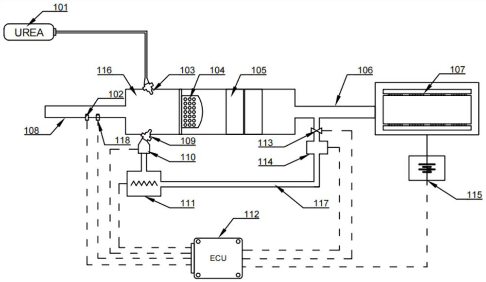
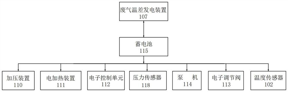
[0026] The present invention provides a device for reducing urea crystallization in an SCR system (device for short). The SCR system includes a urea tank 101, a urea nozzle 103, a mixer 104, a catalytic converter 105, an air outlet pipe 106, an air inlet pipe 108, and an air mixing chamber 116; between the air inlet pipe 108 and the air outlet pipe 106, a gas mixing chamber 116, a mixer 104 and a catalytic converter 105 are arranged in sequence according to the gas flow direction; the beginning of the air inlet pipe 108 is connected to the DPF system, and the exhaust gas processed by the DPF system enters the SCR system; the urea tank 101 is connected to the urea nozzle 103 through a pipeline; the end of the urea nozzle 103 is located in th...


PUM


Abstract

The invention discloses a device and method for reducing urea crystals of an SCR system. The device comprises a temperature sensor, a pressure sensor, a heating and pressurizing gas nozzle, a pressurizing device, an electric heating device, an electronic regulating valve, a pump machine, a waste gas temperature difference power generation device, a storage battery, a recycling waste gas pipe and an electronic control unit. By means of the device, aiming at the low-temperature working condition, waste gas reduced by the SCR system is heated, recycled and injected into the SCR system, and therefore the reaction temperature of NOx and a urea aqueous solution is increased. The reaction temperature is increased, so that the probability of forming a liquid film is reduced, and the generation of the urea crystals is reduced. Meanwhile, the urea aqueous solution and the heated recycled waste gas are oppositely jetted in the SCR system, so that airflow disturbance in a pipe is increased, the probability of forming the liquid film is reduced, and the urea aqueous solution and the recycled waste gas are fully mixed and fully reacted. Meanwhile, heat in waste gas is utilized to generate power by adopting a waste gas temperature difference power generation technology, power is supplied to electric appliances in the device, and energy conservation and emission reduction are achieved.

Description

technical field [0001] The invention belongs to the field of emission control of internal combustion engines, in particular to a device and method for reducing urea crystallization in an SCR system. Background technique [0002] Currently, Selective Catalytic Reduction (SCR) technology is the most effective solution to the problem of how to reduce emissions from internal combustion engines. In the SCR system, after the urea aqueous solution (UWS) is in contact with the high-temperature exhaust gas, the urea undergoes hydrolysis and pyrolysis at high temperature to generate ammonia gas, and then uses ammonia gas as a reducing agent under the action of the catalyst to oxidize the nitrogen in the exhaust gas substances (NOx) are reduced to nitrogen and water. [0003] However, under low temperature conditions, that is, when the engine works under low load and the exhaust gas temperature is low, the decomposition process of urea will be accompanied by the generation of a large ...

Claims


Application Information

Patent Timeline
Patent Type & Authority Applications(China)
IPC IPC(8): F01N3/20F01N9/00F01N11/00
CPCF01N3/2066F01N3/2013F01N11/002F01N9/00F01N2610/02F01N2610/148F01N2610/1486Y02T10/12Y02T10/40
Inventor 张尧刘鑫李孟涵刘晓日张铁臣
Owner HEBEI UNIV OF TECH
Why Eureka
Try Eureka