Synthetic lubricating oil composition

A technology of lubricating oil composition and condensate, which is applied in the field of lubricating oil composition of oil and gas lubricating devices, can solve problems such as blockage of distributor conveying pipelines, poor lubrication of lubrication points, insufficient refining depth, etc., and achieves reduction of wear and high temperature. The effect of coking and technical difficulty

Pending Publication Date: 2022-01-21
PETROCHINA CO LTD
View PDF12 Cites 3 Cited by
  • Summary
  • Abstract
  • Description
  • Claims
  • Application Information

AI Technical Summary

Problems solved by technology

[0009] At present, since the initial application of oil-air lubrication devices in my country, most of them use ordinary medium and heavy-duty industrial gear oil lubricants. Although these products can meet the requirements of general oil-air lubrication devices for oil lubrication performance, they are not suitable for high-temperature environments and low-temperature environments. Poor adaptability to harsh working conditions, mainly manifested in: 1) Poor high temperature resistance, easy to oxidize and deteriorate; 2) Easy to coke, causing the bearing to be stuck and scrapped; 3) Poor viscosity-temperature characteristics, low viscosit

Method used


Image

  • Synthetic lubricating oil composition

Examples


Embodiment 1

[0051] The lubricating oil composition of this embodiment, it comprises: the EO / PO random water-insoluble polyether base oil (component A) of the butyl termination of 95.68wt%; The saturated dipentaerythritol ester of neopentyl decanoate of 3.0wt% (component B); 0.30wt% tricresyl phosphate and 0.2wt% diisooctyl phosphate stearylamine salt (component C); 0.02wt% benzotriazole dioctylamine formaldehyde condensate (component D ); 0.20wt% isopropyl isooctyl phosphate dodecylamine salt (component E); 0.40wt% 2,6-di-tert-butyl-p-cresol and 0.20wt% dialkyldiphenylamine (component Part F); 30 μg / g silicone antifoam (component G).

Embodiment 2

[0053] The lubricating oil composition of this embodiment, it comprises: the EO / PO random water-insoluble polyether base oil (component A) of the butyl termination of 93.68wt%; The saturated dipentaerythritol ester of neopentyl decanoate of 5.0wt% (Component B); 0.30 wt% tricresyl phosphate and 0.2 wt% butyl isooctyl phosphite-N,N-dibutylamine salt (component C); 0.02 wt% benzotriazole dioctylamine formaldehyde condensation 0.20 wt% dodecenylsuccinate half ester (component E); 0.40 wt% of 2,6-di-tert-butyl-p-cresol and 0.20 wt% of dialkyldiphenylamine (Component F); 30 μg / g silicone antifoam (component G).

Embodiment 3

[0055] The lubricating oil composition of this embodiment, it comprises: the EO / PO random water-insoluble polyether base oil (component A) of 93.68wt% butyl termination; 5.0wt% trimellitate (component B ); 0.30 wt% tricresyl phosphate and 0.2 wt% 2,5-dimercaptothiadiazole-N,N-dibutylamine salt derivative (component C); 0.02 wt% benzotriazole dioctylamine Formaldehyde condensate (component D); 0.20 wt% barium dinonylnaphthalene carboxylate (component E); 0.40 wt% of 2,6-di-tert-butyl-p-cresol and 0.20 wt% of dialkyldianiline (Component F); 30 μg / g silicone antifoam (component G).

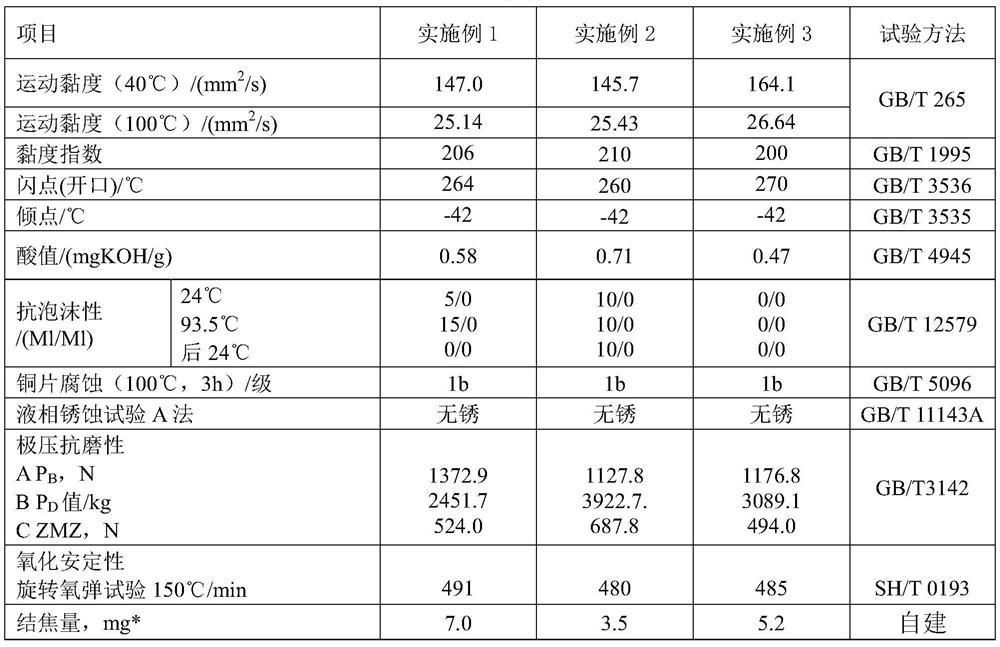
[0056] The main physical and chemical properties of the lubricating oil compositions of Example 1, Example 2, and Example 3 are shown in Table 1.

[0057] Table 1

[0058]


PUM

PropertyMeasurementUnit
Pour pointaaaaaaaaaa

Abstract

The invention relates to a synthetic lubricating oil composition. The composition comprises the following components: 82.0 to 96.33 wt% of base oil, 3 to 10 wt% of ester oil, 0.1 to 3.0 wt% of an extreme pressure anti-wear additive, 0.02 to 1.0 wt% of a metal deactivator, 0.05 to 1.0 wt% of an antirust corrosion inhibitor, 0.5 to 3.0 wt% of an antioxidant additive and 10 to 200 [mu] g/g of an antifoaming agent; wherein the base oil is water-insoluble polyether polyalkylene glycol, and the ester oil is saturated polyol ester and/or polybasic acid ester. The lubricating oil composition has the advantages of excellent viscosity-temperature performance, excellent low-temperature performance, excellent oxidation stability, excellent high-temperature cleaning performance, excellent extreme pressure antiwear property, good rust and corrosion resistance and good foam resistance, and can quickly form an oil film, reduce the operation temperature, reduce the high-temperature coking property and reduce the wear between bearing tooth surfaces.

Description

technical field [0001] The invention relates to a lubricating oil composition, in particular to a lubricating oil composition used for oil-air lubricating devices of large-scale continuous casting machines and continuous rolling mills in the metallurgical industry. Background technique [0002] The mechanism of oil-air lubrication is that lubricating oil and compressed air form a two-phase mixed oil flow in the oil-air mixer. The lubricating oil and compressed air in the two-phase mixed oil flow are not really fused, but driven by the action of compressed air to lubricate. The oil adheres around the pipe wall in the form of an oil film and moves forward at a slow speed. When it is about to reach the outlet of the oil flow, the oil film becomes thinner and thinner, and becomes one piece, and finally flows in extremely fine continuous oil droplets. Spray onto lubrication points. It should be emphasized that the flow rate of oil in the oil-air pipe is much smaller than that of...

Claims


Application Information

Patent Timeline
IPC IPC(8): C10M169/04C10N30/06C10N30/08C10N30/12C10N30/10C10N30/18C10N30/04C10N40/02C10N40/04
CPCC10M169/044C10M2209/1045C10M2209/1055C10M2209/1085C10M2207/283C10M2223/041C10M2223/043C10M2215/04C10M2215/223C10M2207/026C10M2215/064C10M2229/04C10M2207/288C10M2207/285C10M2219/106C10M2207/141
Inventor 于海张遂心周康黄芸琪梁依经
Owner PETROCHINA CO LTD
Why Eureka
Try Eureka