Assembly method of ultrafast laser reflector for miniature laser gyroscope

A laser gyroscope and ultrafast laser technology, applied in laser welding equipment, chemical instruments and methods, Sagnac effect gyroscopes, etc., can solve the problem that glass powder sintering technology is difficult to break through, and optical glue technology is difficult to meet strong impact requirements, etc. problems, to achieve the effect of quality protection, high connection strength, and good roughness

Active Publication Date: 2022-04-08
XIAN SINO HUAXIN MEASUREMENT & CONTROL
View PDF22 Cites 0 Cited by
  • Summary
  • Abstract
  • Description
  • Claims
  • Application Information

AI Technical Summary

Problems solved by technology

[0007] To sum up, optical glue technology is difficult to meet the requirements of strong impact, and glass powder sintering technology is difficult to break through in a short period of time. It is necessary to find a new assembly method for laser gyro mirrors that is resistant to strong impact to meet the large number of markets. need

Method used


Image

  • Assembly method of ultrafast laser reflector for miniature laser gyroscope

Examples


Embodiment 1

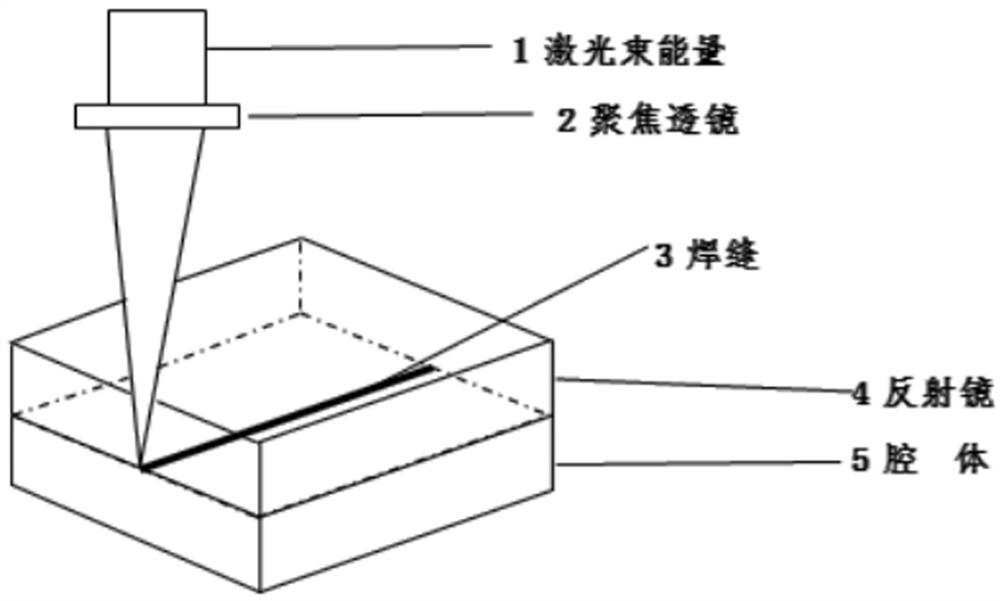
[0027] This example provides an assembly method of an ultrafast laser mirror for a micro-laser gyroscope. The assembly schematic diagram is as follows figure 1 shown, including the following steps:

[0028] Step (1): Use a cleaning agent to clean the laser gyro cavity-0-level glass-ceramic cavity and the mirror-0-level glass-ceramic mirror, and then fix the optical adjustment tooling with the aid of precision tooling and optical equipment; , the cleaning agent was prepared by the following method: 12 parts of choline hydroxide, 4 parts of tetrabutylammonium hydroxide, 20 parts of N-methylpyrrolidone, 0.3 parts of sorbitol-based polyether polyol and 30 parts of ultrapure water Mix separately, and stir at room temperature for 45 min to prepare;

[0029] Step (2): Transfer the laser gyro cavity and mirror fixed in step (1) to the welding area of ​​the laser welding machine for laser welding; among them, the laser welding process parameters are: laser power 980w, welding speed 15...

Embodiment 2

[0035] This example provides a method for assembling an ultrafast laser reflector for a micro-laser gyro. The only difference from Example 1 is that the reflector is a quartz glass reflector, and the cleaning agent consists of the following components by mass: choline hydroxide 15 parts, 5 parts of tetrabutylammonium hydroxide, 25 parts of N-methylpyrrolidone, 0.1 part of sorbitol-based polyether polyol and 35 parts of ultrapure water; the rest of the steps and parameters are the same.

[0036] The impact test was carried out. The laser micro-welded resonator in this example passed the 10,000 g unprotected impact test. After the impact, the performance of the test resonator met the design index requirements; and a further 35,000 g impact test was carried out, and the performance of the resonant cavity also met the design index after the impact test. Require.

[0037] In this example, the average roughness of the cleaned laser gyro cavity and reflector surface was also measured...

Embodiment 3

[0039] This example provides an assembly method of an ultrafast laser reflector for a micro-laser gyroscope. The difference from Example 1 is that the reflector is a K9 optical glass reflector, and the laser welding process parameters are: laser power 1080w, welding speed 160mm / s, the welding path is a hyperbola, and the defocus is +2 mm; the rest of the steps and parameters are the same.

[0040] The impact test was carried out. The laser micro-welded resonator in this example passed the 10,000 g unprotected impact test. After the impact, the performance of the test resonator met the design index requirements; and a further 35,000 g impact test was carried out, and the performance of the resonant cavity also met the design index after the impact test. Require.


PUM

PropertyMeasurementUnit
melting pointaaaaaaaaaa

Abstract

The invention discloses an assembling method of an ultrafast laser reflecting mirror for a miniature laser gyroscope, and belongs to the technical field of laser gyroscope reflecting mirror assembly.The assembling method comprises the following steps that 1, a laser gyroscope cavity and a reflecting mirror are cleaned through a cleaning agent, and then an optical adjusting tool is fixed; and (2) transferring the laser gyroscope cavity and the reflector which are fixed in the step (1) to a welding area of a laser welding machine, and carrying out laser welding. The assembling method is based on the laser micro-welding technology, in the welding process of the laser gyroscope reflector and the resonant cavity, the quality of a coating layer of the reflector is well protected, the whole welding process is short in time and easy to operate, batch production can be achieved, and the production efficiency can be greatly improved; and through an impact test, the resonant cavity subjected to laser micro-welding passes a 10000 g unprotected impact test, and the performance of the resonant cavity is tested to meet the design index requirement after impact.

Description

technical field [0001] The invention relates to the technical field of laser gyroscope assembly technology, in particular to an assembly method of an ultrafast laser reflector for a miniature laser gyroscope. Background technique [0002] It has been 60 years since the concept of the laser gyroscope was proposed in 1961. During its development, the assembly method of the laser gyroscope has also undergone rapid changes, especially the assembly of the resonator optical components, the core component of the laser gyroscope. The method, with the continuous improvement of the level of optical cold processing super polishing, also changes accordingly. Its assembly method has gone through the following schemes: gluing, pressure sealing, brazing, light glue, and sintering. At present, the mainstream method of assembling optical parts of laser gyro resonator cavity is optical glue and glass frit sintering. [0003] The assembly method of domestic laser gyro resonator optical parts...

Claims


Application Information

Patent Timeline
Patent Type & Authority Applications(China)
IPC IPC(8): B23K26/21B23K26/60C11D1/72C11D3/28C11D3/30C11D3/60G01C19/72
Inventor 徐金涛刘尚波毛建朋李莉石念宝王嘉曹辉孔小花杨一凤许慎诺
Owner XIAN SINO HUAXIN MEASUREMENT & CONTROL
Why Eureka
Try Eureka