Tail cooling rotor engine

A rotary engine and rotor technology, applied in engine components, machines/engines, liquid fuel engines, etc., can solve the problems of gas failure, low thermal cycle efficiency, and high fuel consumption, and achieve low vibration, low noise, and overhaul cycles. long effect

Pending Publication Date: 2022-04-12
李笑一
View PDF0 Cites 0 Cited by
  • Summary
  • Abstract
  • Description
  • Claims
  • Application Information

AI Technical Summary

Problems solved by technology

When this type of rotary engine is used for shaft output, the high-temperature and high-pressure airflow is discharged by self-expansion between the open impeller blades through the expansion of the turbine blades, and a considerable proportion of the gas fails to play its role
Moreover, the existing turbojet or turbofan engines are only suitable for fluid load environments, and there is a serious surge phenomenon for land loads, so high idle speed mode must be used to maintain its stable working state, the thermal cycle efficiency is low, and its fuel consumption is extremely high

Method used


Image

  • Tail cooling rotor engine
  • Tail cooling rotor engine
  • Tail cooling rotor engine

Examples


Embodiment 1

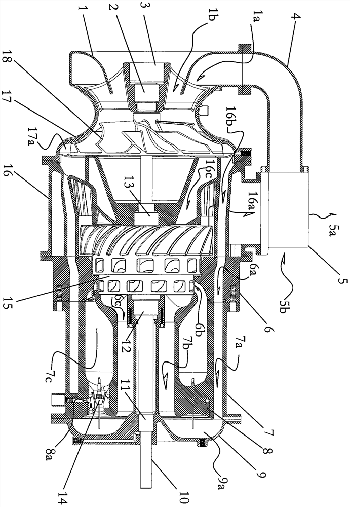
[0040] as attached Figure 1-13 As shown, a tail-cooled rotor engine includes a compressor A, a rotor machine B, a burner C, a heat cycle heat exchanger 5 and a preheating air pipe 4; the compressor A includes an intake cover 1, a bearing A2, Start clutch 3, housing 17, compressed air impeller 18, left side structure and main shaft 10 of cold flow exhaust gas combination body 16; described rotor machine B comprises the right side structure of cold flow tail gas combination body 16, bearing B13, rotor 15, bearing C12, the left side structure of the injection recoil seat 6 and the main shaft 10; the burner C, including the right side structure of the injection recoil seat 6, the main cylinder 7, the burner 14 and the end cover 9; the main cylinder There is a main shaft 10 in the middle of 7, and the center of the end cover 9 passes through the bearing D11; the heat cycle heat exchanger 5 is a tubular structure, including a cold air inlet 5b and an exhaust gas outlet 5a; the comp...

Embodiment 2

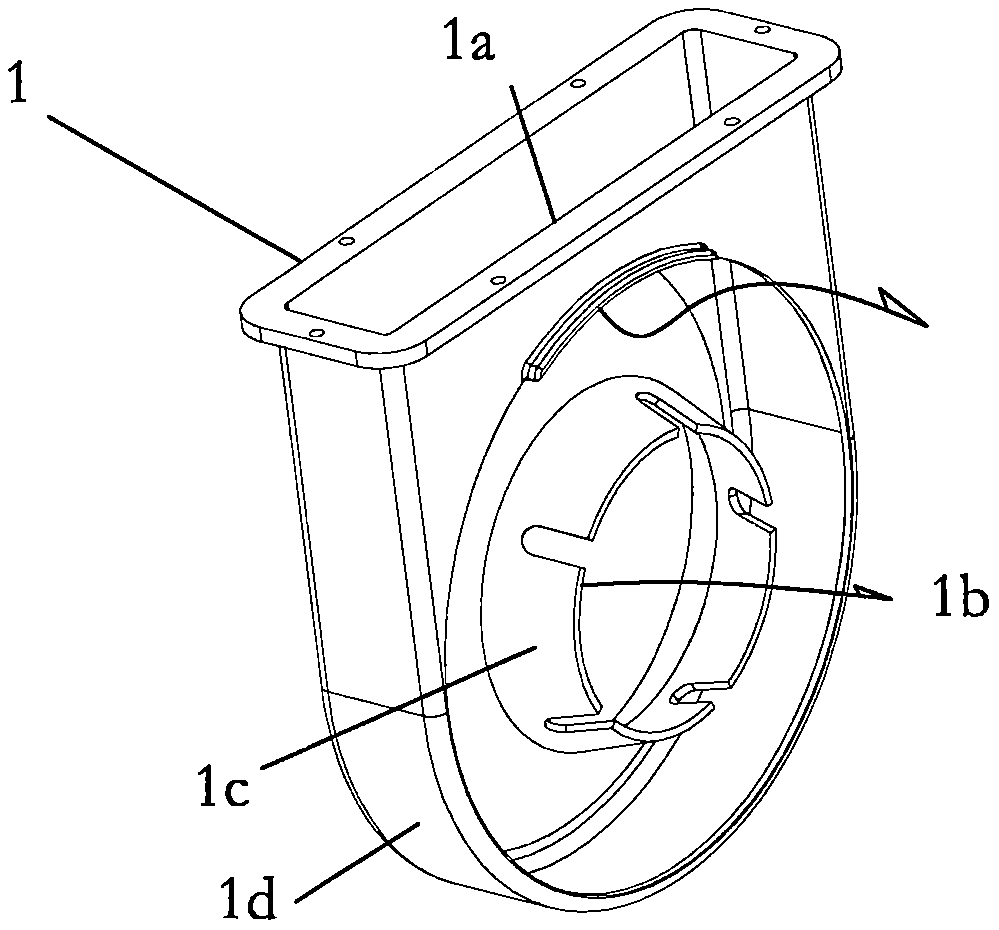
[0042] as attached figure 1 , 2 As shown, in the tail-cooled rotary engine of the present invention, the air intake cover 1 includes a shell 1d and a guide cone 1d, and the air intake passage is divided into a peripheral preheated air passage 1a and an intermediate cold air passage 1b; The preheated air outlet of the heater 5 is connected with the peripheral preheated channel 1a of the air intake hood 1 through the preheated air pipe 4 .

Embodiment 3

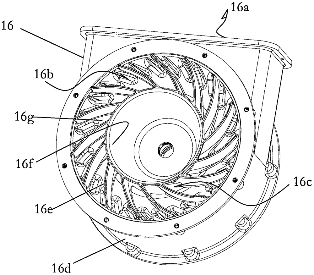
[0044] as attached figure 1 , 3 As shown in -5, in the tail-cooled rotor engine of the present invention, the cold flow exhaust gas combination 16 has an outer cylinder A16d, and the inner wall of the left section of the outer cylinder 16d is connected with a conical flow guide 16g and a flow guide extension. 16h, there is a conical body 16f inside the conical diversion platform 16g and the diversion platform extension tube 16h; there are diversion ribs on the inner wall of the left section of the outer cylinder A16d, the left side of the diversion conical platform 16g and the outer surface of the conical body 16e, the deflector rib 16e extends to the left to the outer surface of the cone 16f and the inner surface of the deflector platform extension cylinder 16h; the cold flow exhaust combination body 16 has an inner cylinder A16i1, a middle cylinder A16i2 and a bottom 16i3 Formed annular U-shaped groove, the heat exchange flat tube 16j is connected between the opening of the...


PUM


Abstract

An air compression cavity of an air compressor A of the tail cooling rotor engine is communicated with an air collection cavity of an end cover from left to right through a peripheral cold flow channel A of a cold flow tail gas combination body, a peripheral cold flow channel B of an injection backflushing seat and a peripheral cold flow channel C of a main cylinder body; an air compression cavity of the air compressor A is communicated with an air collection cavity of the end cover from left to right through a middle cold flow channel A of the cold flow combination body, a middle cold flow channel B of the rotor, a middle cold flow channel C of the jet backflushing seat and a middle cold flow channel D of the main cylinder. The heat engine is high in efficiency, low in requirement for high-temperature performance of blade materials, low in rotor rotating speed and large in angular momentum, and is suitable for fluid-loaded aircrafts, ships and the like.

Description

technical field [0001] The invention relates to a tail-cooled rotor engine, which belongs to the technical field of gas turbines. Background technique [0002] In the gas turbine in the prior art, the main shaft driven by the blades generates torque to drive the load or output power. Due to the structure of the blade, the moment of inertia or angular momentum of the main shaft depends on the high speed. Once the speed drops, the ability of the main shaft to drive the load or the output power drops sharply or even fails to drive the load. The working speed of gas turbines in the prior art is usually 20,000-50,000 rpm, or even higher. But high speed must be driven by high-speed gas, and high-speed gas requires high temperature and high pressure. Not only the high-speed airflow may lead to incomplete conversion of thermal engine efficiency, but also low thermal efficiency. It also requires blade materials to have superior high-temperature performance, and the blade temperature...

Claims


Application Information

Patent Timeline
Patent Type & Authority Applications(China)
IPC IPC(8): F04D25/08F04D17/12F04D29/28F04D29/42F02C3/08F02C3/14F02C3/22F02C3/34F23R3/36F23R3/42F02C7/266F02C7/22F01D9/04F02C9/26
CPCF04D25/08F04D17/127F04D29/286F04D29/285F04D29/4206F02C3/08F02C3/14F02C3/22F02C3/34F23R3/36F23R3/42F02C7/266F02C7/22F01D9/047F02C9/263F05D2220/3216Y02T10/12
Inventor 李笑一
Owner 李笑一
Why Eureka
Try Eureka