Hydrogen impurity purification device for fuel cell

A purification device, fuel cell technology, applied in gas treatment, chemical instruments and methods, membrane technology, etc., can solve the problems of large occupied area, limited use, complex equipment, etc., to achieve simple device, prevent potential deviation, and complexity. low effect

Active Publication Date: 2022-04-22
BEIJING SINOHYTEC
View PDF13 Cites 0 Cited by
  • Summary
  • Abstract
  • Description
  • Claims
  • Application Information

AI Technical Summary

Problems solved by technology

[0005] In view of the above analysis, the embodiment of the present invention aims to provide a hydrogen impurity purification device for fuel cells to solve the problems of the existing PSA technology with many processes, complex equipment, and large occupied area, resulting in limited use

Method used


Image

  • Hydrogen impurity purification device for fuel cell
  • Hydrogen impurity purification device for fuel cell

Examples


Embodiment 1

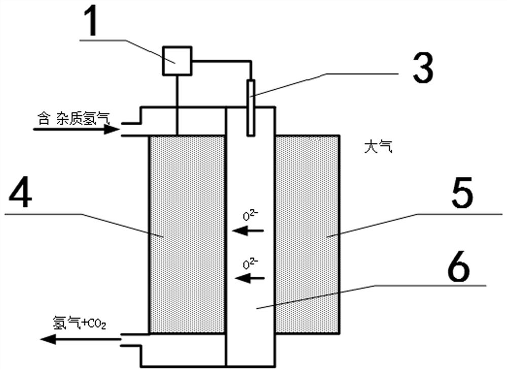
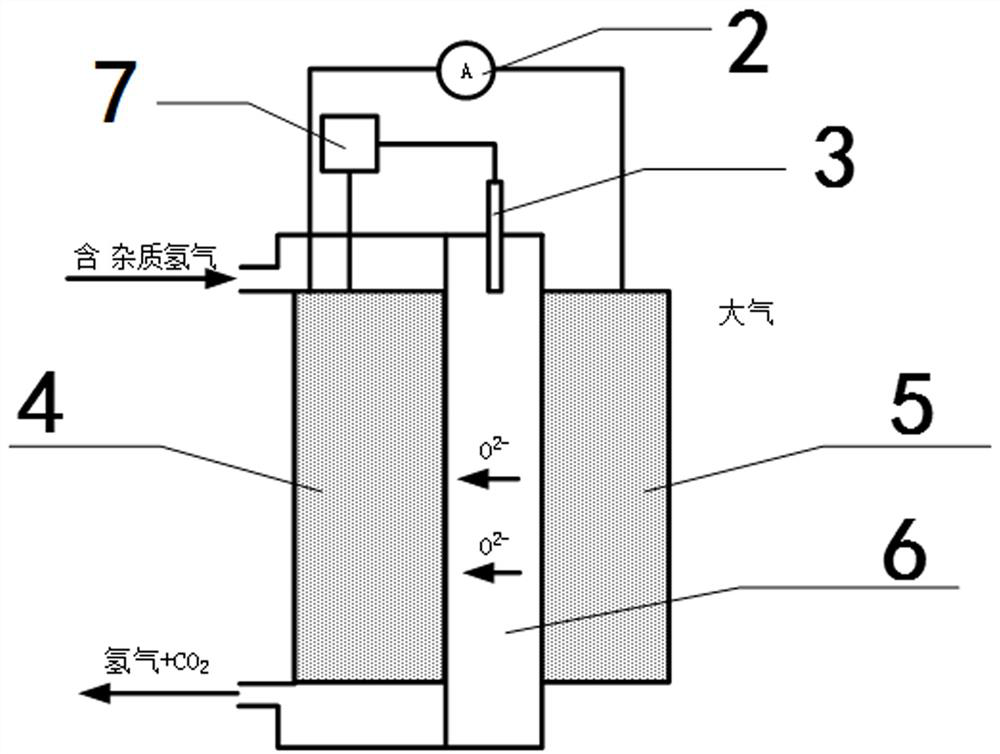
[0051] An embodiment of the present invention discloses a hydrogen impurity purification device for a fuel cell, including a solid-state electrochemical reactor and a controller.

[0052] The solid state electrochemical reactor further comprises an anode diffusion electrode layer 4 , an electrolyte layer 6 , a cathode diffusion electrode layer 5 and a reference electrode 3 . The electrolyte layer 6 serves to transport oxygen ions. The two sides of the anode diffusion electrode layer 4 are respectively provided with an inlet for hydrogen gas to be purified and an outlet for hydrogen gas after purification. The cathode diffusion electrode layer 5 is in contact with air, and is separated from the anode diffusion electrode layer 4 by an electrolyte layer 6 . The reference electrode 3 is located in the electrolyte layer 6, such as figure 1 shown.

[0053] The controller is used to control the potential of the anode diffusion electrode layer 4 of the solid-state electrochemical r...

Embodiment 2

[0056] Improvements are made on the basis of Example 1, and the impurities include at least one of carbon monoxide, hydrogen sulfide, nitrogen oxides, and ammonia. Also, the hydrogen purification device is used to convert carbon monoxide (CO) into carbon dioxide (CO 2 ), or, hydrogen sulfide (H 2 S) converted to sulfuric acid (H 2 SO 4 ), alternatively, nitrogen oxides (NO X ) into nitrogen (N 2 ) and oxygen (O 2 ), or, ammonia (NH 3 ) into nitrogen (N 2 ) and water.

[0057] Preferably, a catalyst is distributed in both the anode diffusion electrode layer 4 and the cathode diffusion electrode layer 5; and the catalyst is a metal oxide.

[0058] Preferably, for carbon monoxide or hydrogen sulphide impurities, the catalyst comprises nickel oxide; for nitrogen oxides or ammonia impurities, the catalyst comprises zirconia.

[0059] Preferably, preferably, the ionic electrolyte can adopt but not limited to Bi 2 V 0.9 Cu 0.1 o 5.35-δ (See "Bi 2 V 0.9 Cu 0.1 o 5.35-...


PUM


Abstract

The invention provides a hydrogen impurity purification device for a fuel cell, belongs to the technical field of fuel cells, and solves the problems that the existing PSA (Pressure Swing Adsorption) technology has more working procedures, complicated equipment and large occupied area, so that the use is limited. The apparatus includes a solid state electrochemical reactor and a controller. Wherein the solid-state electrochemical reactor further comprises an anode diffusion electrode layer, an electrolyte layer for transmitting oxygen ions, a cathode diffusion electrode layer and a reference electrode. A to-be-purified hydrogen inlet and a purified hydrogen outlet are respectively formed in two sides of the anode diffusion electrode layer; the cathode diffusion electrode layer is in contact with air and is isolated from the anode diffusion electrode layer through the electrolyte layer; the reference electrode is arranged in the electrolyte layer; and the controller is used for controlling the potential of the anode diffusion electrode layer of the solid-state electrochemical reactor to be the oxidation-reduction potential of the impurities after being started, so that the impurities are subjected to oxidation-reduction reaction to be converted into other component substances which have no or less influence on the fuel cell.

Description

technical field [0001] The invention relates to the technical field of fuel cells, in particular to a hydrogen impurity purification device for fuel cells. Background technique [0002] Among the existing hydrogen purification technologies, pressure swing adsorption (PSA) is the most widely used. The physical process involved is to pass dry hydrogen containing impurities into the adsorption tower from bottom to top, use molecular sieves to absorb hydrogen and impurities under different pressures, remove impurities in the tower, and collect pure hydrogen at the outlet. When the adsorption reaches saturation, it enters the decompression regeneration process, desorbs and discharges the adsorbed impurities, and the four adsorption towers alternately adsorb and regenerate to complete the purification of hydrogen. [0003] PSA technology is based on the physical adsorption of gas molecules on the internal surface of the porous solid substance adsorbent, using the adsorbent to eas...

Claims


Application Information

Patent Timeline
Patent Type & Authority Applications(China)
IPC IPC(8): B01D53/32B01D53/86B01D53/52B01D53/56B01D53/58B01D53/62
CPCB01D53/326B01D53/864B01D53/8634B01D53/8631B01D53/8612B01D2257/502Y02E60/50
Inventor 方川曹季冬李飞强张国强
Owner BEIJING SINOHYTEC
Why Eureka
Try Eureka