Evaluation system for MEMS gas sensor

A gas sensor and gas technology, applied in the field of evaluation systems, can solve the problems of test gas environmental pollution, unstable test environment, low degree of automation, etc., to increase the relative adsorption area, improve air tightness and result accuracy, measurement Precise results

Pending Publication Date: 2022-07-22
SICHUAN UNIV
View PDF10 Cites 0 Cited by
  • Summary
  • Abstract
  • Description
  • Claims
  • Application Information

AI Technical Summary

Problems solved by technology

[0004] Aiming at the deficiencies of the prior art, the present invention provides an evaluation system for MEMS gas sensors, which solves the problem of the low degree of automation of the existing evaluation system, the large error of the measured data, the small test range, and the unstable test environment. Poor repeatability, the escaped test gas can easily cause environmental pollution

Method used


Image

  • Evaluation system for MEMS gas sensor
  • Evaluation system for MEMS gas sensor
  • Evaluation system for MEMS gas sensor

Examples


Embodiment 1

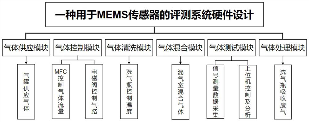
[0025] A MEMS gas sensor detection device is provided, such as figure 1 As shown, it includes a gas supply module, a gas control module, a gas cleaning module, a gas mixing module, a gas testing module and a gas processing module.

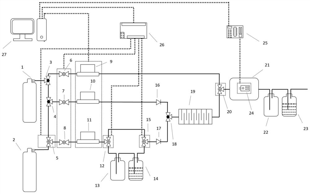
[0026] Specifically, as figure 2 As shown, the MEMS gas sensor detection system includes nitrogen cylinder 1, other gas cylinders 2, all-way three-way valves 3, 4, 18, two-position three-way solenoid valves 5, 12, 15, 20, and two-position two-way solenoid valves 6, 7, 8, MFC9, 10, 11, buffer bottle 13, 22, gas washing bottle 14, 23, one-way valve 16, 17, gas mixing chamber 19, cavity 21, standard gas sensor 24, microcontroller 25, PLC26 and PC27.

[0027] Specifically, the gas path adopts a silicone tube with an inner diameter of 6.5 mm and an outer diameter of 10 mm, and the joint between the device and the silicone tube adopts a two-point turn quick-release joint.

[0028] Specifically, one end of the above-mentioned two-point rotary quick re...

Embodiment 2

[0040] A method for detecting MEMS gas sensors under different humidity conditions in a test system is proposed:

[0041] Specifically, as Figure 5 As shown, the host computer software in the PC27 inputs the program into the PLC26 through the network port 113, and sets the PLC to the RUN mode, the 24V DC power supply 101 supplies power to the PLC, and the 24V DC power supply 103 forms a loop with all the reset buttons to connect to the terminal 102, etc. To supply power to the input signal, the 24V DC power supply 112 supplies power to the solenoid valve.

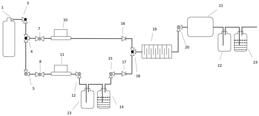
[0042] Specifically, as image 3 As shown, open the nitrogen bottle 1 to make nitrogen flow into the system, which is the two-position two-way solenoid valve 6, and the two-position three-way solenoid valve 20 is energized to conduct the first passage.

[0043] Specifically, connect the MFC9 to the computer to set the nitrogen flow rate and enter the cavity. After stabilization, record the MEMS gas sensor and standard ga...

Embodiment 3

[0049] A method for detecting MEMS gas sensors under dry mixed gas conditions in the test system is proposed:

[0050] Specifically, as Figure 5 As shown, the host computer software in the PC27 inputs the program into the PLC26 through the network port 113, and sets the PLC to the RUN mode, the 24V DC power supply 101 supplies power to the PLC, and the 24V DC power supply 103 forms a loop with all the reset buttons to connect to the terminal 102, etc. To supply power to the input signal, the 24V DC power supply 112 supplies power to the solenoid valve.

[0051] Specifically, the nitrogen cylinder 1 is turned on to allow nitrogen to flow into the system, which is the two-position two-way solenoid valve 6, and the two-position three-way solenoid valve 20 is energized to conduct the first passage.

[0052] Specifically, connect the MFC9 through the computer, set the nitrogen flow rate and enter the cavity, and record the MEMS gas sensor and standard gas sensor readings displaye...


PUM


Abstract

The invention discloses an evaluation system for an MEMS gas sensor, the evaluation system comprises a gas supply module, a gas control module, a gas cleaning module, a gas mixing module, a gas testing module and a gas processing module, the gas supply module comprises two gas cylinders, and the invention relates to the technical field of MEMS gas sensors. According to the evaluation system for the MEMS gas sensor, the gas tightness and the result accuracy of the device are effectively improved, the response time of the MEMS gas sensor is shortened by using a small-size cavity, the relative adsorption area of the MEMS gas sensor to gas is increased, the measurement result is more accurate, the gas mixing chamber is arranged behind the second passage and the third passage, the gas is uniformly mixed, and the measurement accuracy is improved. The gas introduced into the cavity is the mixed gas with stable physical properties, the gas environment has more advantages in the aspect of accurate measurement of the MEMS gas sensor, and compared with manual control, the gas flow of a passage can be more continuously changed, so that characteristic response curves of the MEMS gas sensor under different parameter conditions can be obtained.

Description

technical field [0001] The invention relates to the technical field of MEMS gas sensors, in particular to an evaluation system for MEMS gas sensors. Background technique [0002] MEMS gas sensor is a sensor that integrates electromechanical sensitive components and processing circuits based on various physical effects on a chip using integrated circuit technology and micromachining methods. Since the advent of the first silicon micro pressure sensor in 1962, MEMS The continuous progress and development of technology has greatly promoted the improvement of the performance of gas sensors. In recent years, with the development of microelectronics technology, integrated circuit technology and processing technology, MEMS gas sensors are more because of their small size, light weight and low power consumption. , high reliability, high sensitivity, easy integration and resistance to harsh working environments and other advantages, gradually occupy the sensor market, has been favore...

Claims


Application Information

Patent Timeline
Patent Type & Authority Applications(China)
IPC IPC(8): G01N27/12G01N1/34G01N1/38
CPCG01N27/12G01N1/34G01N1/38
Inventor 王竹卿母雨鑫温友福刘媛宋依林汝小龙刘童
Owner SICHUAN UNIV
Why Eureka
Try Eureka