Anodic oxygenation method and operation apparatus thereof
What is AI technical title?
AI technical title is built by PatSnap AI team. It summarizes the technical point description of the patent document.
A technology of anodizing and anodizing film, applied in anodizing, chemical instruments and methods, transportation and packaging, etc., can solve problems such as unsatisfactory, weakened oxidizing ability, and increased surface resistance of metal bodies.
Inactive Publication Date: 2004-08-25
NIPPON TECH CO LTD
View PDF1 Cites 6 Cited by
Summary
Abstract
Description
Claims
Application Information
AI Technical Summary
This helps you quickly interpret patents by identifying the three key elements:
Problems solved by technology
Method used
Benefits of technology
Problems solved by technology
But this technology is still not ideal, because the oxygen produced by electrolysis near the anode tends to form bubbles and transfer to the air, so their oxidation ability on the surface of the metal body becomes weaker
In addition, the formation of oxygen bubbles leads to an increase in the resistance of the surface of the metal body and a higher voltage is required for processing, so more electrical energy is required, and the heat energy release and energy loss become larger
So it is believed that conventional technology is actually used at lower current densities, such as 2-3A / dm 2 , so the anodizing process cannot be accelerated when using a treatment solution at high temperature or room temperature
Method used
Image
Click on the blue label to locate the original text in one second.
Reading with bidirectional positioning of images and text.
Examples
Embodiment 1
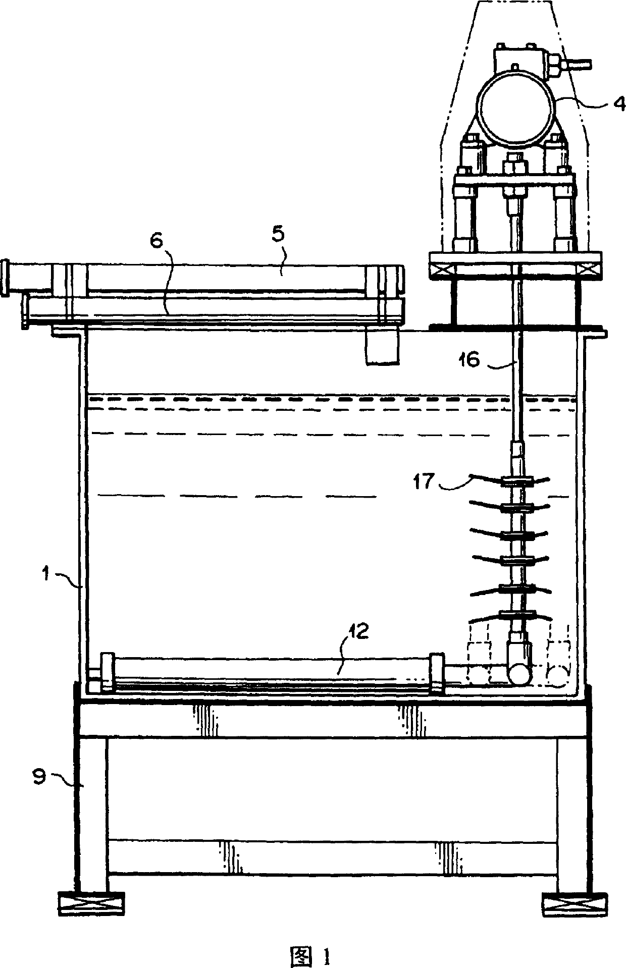
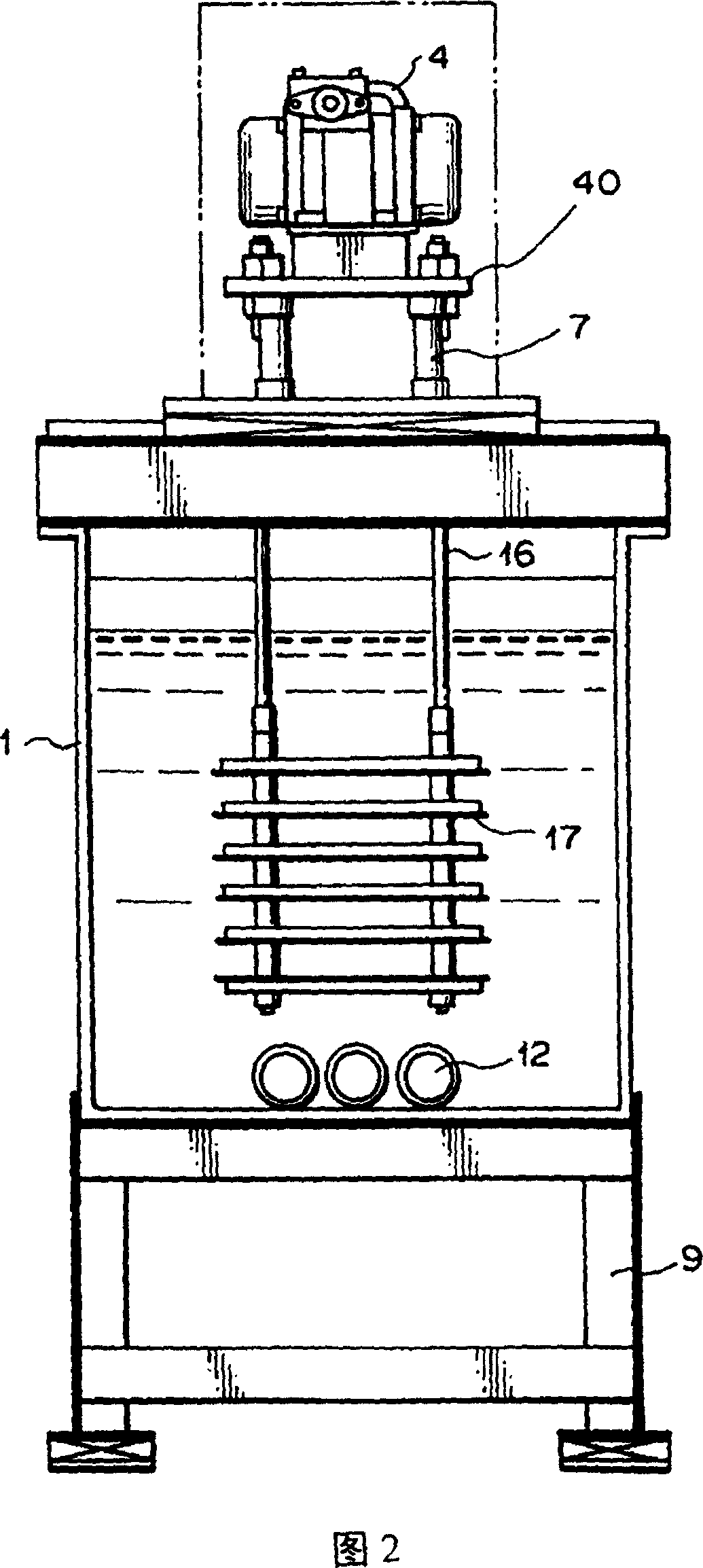
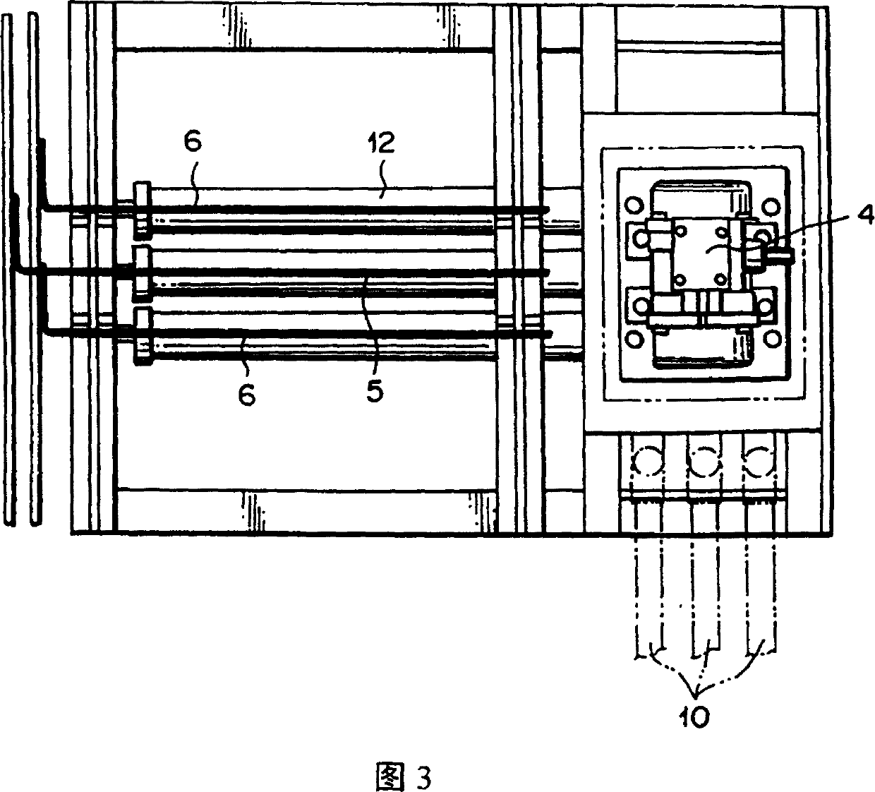
[0146] A device of the type shown in Figures 1-3 is used. The size and volume of each sub-device are as follows:
[0148] The trough used was made of heat-resistant polyvinyl chloride and had a width of 500 mm, a length of 750 mm and a height of 550 mm.
[0149] (2) Vibration flow stirring device
[0150] An ultra-vibrating α3-type stirrer, manufactured by Nippon Techno Co., Ltd., was used.
[0151] Vibration generator: URAS VIBRATOR KEE 3.5-2B, provided by YASKAWA Co., Ltd., 250W×200V×3 phase, controlled by inverter (0.4kW)
[0152] Vibrating vane: effective area 300×100mm, thickness 0.5mm (use 5 vibrating vanes), α=15 degrees (the lowest vane is inclined downward, and the other vanes are inclined upward)
[0222] The anodizing process was carried out under the same conditions as in Example 1, except that the vibration motor output power of the device (A) was 150V, the anode potential was 15V, and the treatment liquid temperature was 30°C, and the treatment time was 5 minutes. The results are shown in Table 3.
Embodiment 3
[0239] The anodizing process was carried out under the same conditions as in Example 1, except that the aluminum plate of the processing target was changed to a duralumin plate made of A5052P (JIS H400).
[0240] Si = 0.25% or less
[0241] Fe = 0.04% or less
[0242] Cu=0.01%
[0243] Mn = 0.01 or less
[0244] Mg=2.2-2.8%
[0245] Cr=0.15-0.35%
[0246] Zn = 0.1 or less
[0247] The results are shown in Table 4
PUM
Property
Measurement
Unit
thickness
aaaaa
aaaaa
pore size
aaaaa
aaaaa
thickness
aaaaa
aaaaa
Abstract
An anodizing treatment process is performed while the following apparatuses (A) to (D) are simultaneously operated: (A) a vibrationally fluidly stirring apparatus for the treatment bath, in which a vibration vane is vibrated at an amplitude of 0.5 to 3.0 mm and at a vibrational frequency of 200 to 800 times per minute to generate vibrational flow in the treatment bath; (B) an aeration apparatus for the treatment bath, which comprises a ceramic diffusing pipe having a pore-size of 10 to 400 mu m and porosity of 30 to 40 %; (C) an apparatus for applying vibration to the metal body through an electrode bar on which the metal body is hung in an amplitude from 0.5 to 1.0 mm and at a frequency of 100 to 300 times per minute; and (D) an apparatus for swinging an electrode bar for suspending the metal body thereon, which generates a swinging motion of the metal body at a swinging amplitude of 10 to 100 mm and a frequency of 10 to 30 times per minute through the electrode bar.
Description
technical field [0001] The invention relates to an anodic oxidation method of vibrating and flowing stirring of a metal body, and an operating device of the method. Background technique [0002] In the field of metal product manufacturing, such as the manufacture of aluminum, aluminum alloy, magnesium, magnesiumalloy, etc., an anodic oxidation film is formed on the surface of the metal body by applying an anodic oxidation method, which requires reducing energy loss and increasing production, especially accelerating anodic oxidation Oxidation process, improving the efficiency of oxide film formation. Moreover, this method also requires accelerating the anodic oxidation process when using a treatment liquid under high temperature or room temperature conditions. [0003] In fact, the biggest problem with the conventional anodizing method is that it takes a long time to form even a very thin oxide film with a thickness of 10-15 μm. Therefore, in the production line of metal p...
Claims
Application Information
Patent Timeline
Application Date:The date an application was filed.
Publication Date:The date a patent or application was officially published.
First Publication Date:The earliest publication date of a patent with the same application number.
Issue Date:Publication date of the patent grant document.
PCT Entry Date:The Entry date of PCT National Phase.
Estimated Expiry Date:The statutory expiry date of a patent right according to the Patent Law, and it is the longest term of protection that the patent right can achieve without the termination of the patent right due to other reasons(Term extension factor has been taken into account ).
Invalid Date:Actual expiry date is based on effective date or publication date of legal transaction data of invalid patent.

