Independent flow-thru capacitor

A flow-through capacitor technology, applied in capacitors, fixed capacitors, through-hole capacitors, etc., can solve the problems of easy leakage, lack of industrial convenience, etc., and achieve the effect of easy output, automatic output, and small dosage

Inactive Publication Date: 2003-05-14
LUXON ENERGY DEVICES CORP
View PDF5 Cites 10 Cited by
  • Summary
  • Abstract
  • Description
  • Claims
  • Application Information

AI Technical Summary

Problems solved by technology

Such a complex FTC structure is prone to liqui...

Method used


Image

  • Independent flow-thru capacitor
  • Independent flow-thru capacitor
  • Independent flow-thru capacitor

Examples


Embodiment 1

[0032] Using the roller coating method, the self-made hydrated iron oxide uniform slurry is coated on the aluminum foil with a size of about 150mm×490mm×0.1mm to form FTC. The slurry is based on the following formula:

[0033] 1g Fe 3 o 4 And 0.03g PVDF (polyethylene fluoride) and 1.5ml NMP (N-methyl-2-

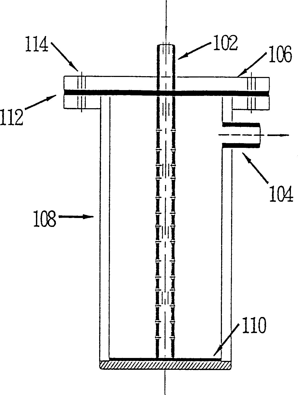
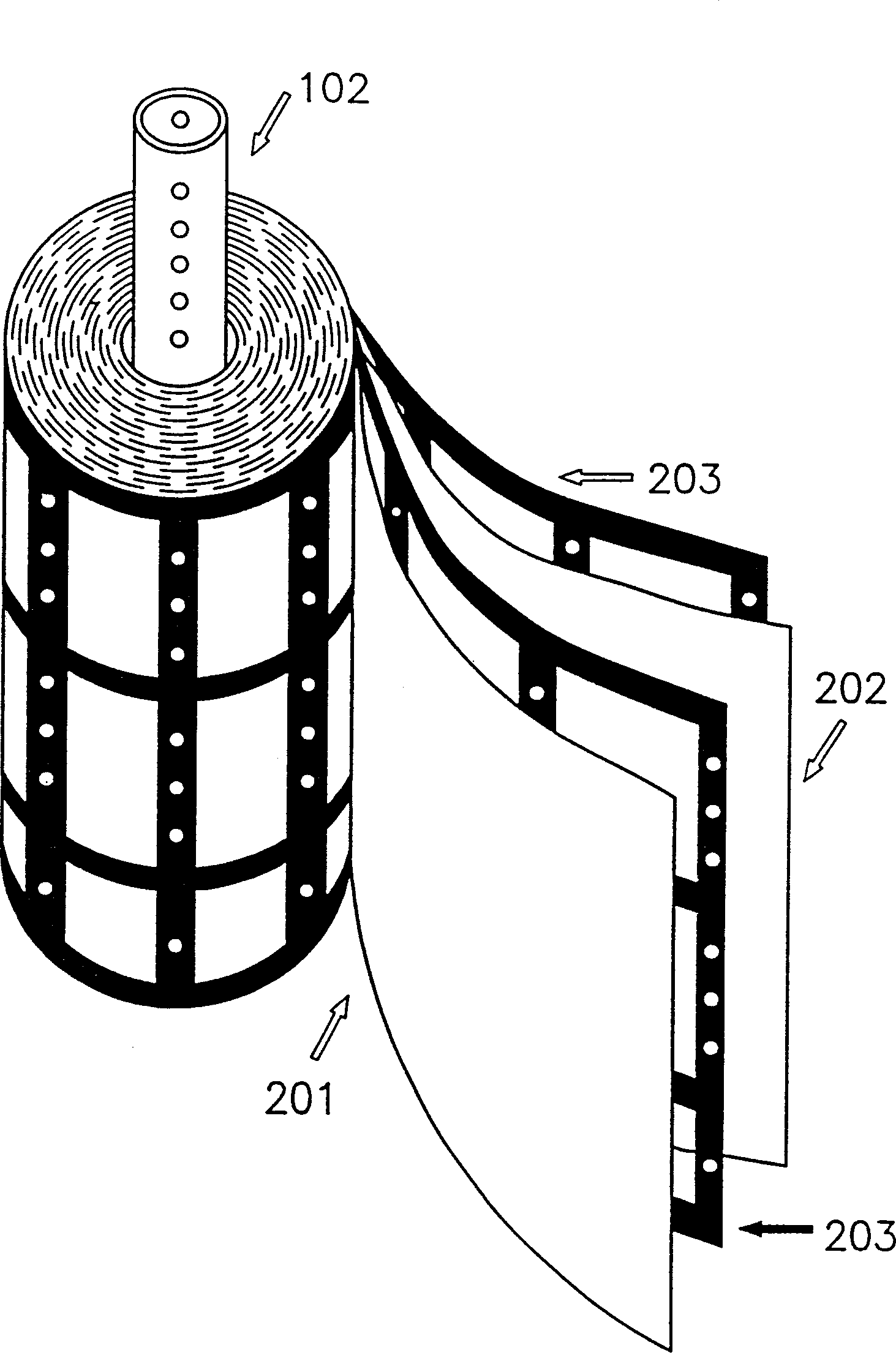
[0034] After irradiating with IR light or other heating devices, the solvent NMP is evaporated, and the electrode and the separator are rolled into such a figure 2 FTC reel shown. The tabs of the base foils of the anode and cathode serve as electrical leads and are connected to a DC power source. Insert the liquid inlet pipe 102 into the center of the reel, and then put the FTC into the plastic container body 108, wherein the inner diameter of the container body 108 is 60mm and the height is 150mm. Then, use bolts and nuts to fix the top cover 106 on the container 108, thereby sealing the container 108, and at the same time extend the two lug wires to the outside of the...

Embodiment 2

[0041] Rinse the spent FTC of Example 1 with deionized water until the effluent shows low conductivity (read the μS value displayed digitally). The following tests were performed with the regenerated FTC.

[0042] Liquid: CuSO 4 Aqueous solution with a conductivity of 1420μS / cm

[0043] Voltage: 1.0DC volts

[0044] Liquid flow rate: 50ml / min

[0045] Number of Cassettes: 2 The conductivity of the first collected 50ml effluent was measured to be 724 μS / cm, indicating that 49% of the ions were removed once the fluid passed through the FTC at very low voltage.

Embodiment 3

[0047] FTC for seawater desalination was prepared using a regeneration method similar to that of Example 2. Seawater from the Pacific Ocean is obtained from somewhere on the west coast of Taiwan. In order to meet the measurement range of the conductivity meter used in the present invention, the sample was diluted 50 times with deionized water. The TDS (Total Dissolved Solids) of the samples used was estimated at 20,000 ppm. Without any pretreatment, the desalination test of diluted seawater was carried out under the following conditions.

[0048] Liquid: Diluted seawater with a conductivity of 793μS / cm

[0049] Voltage: 1.0DC volts

[0050] Liquid flow rate: 50ml / min

[0051] Number of cassettes: 2

[0052] The conductivity of the first collected 50ml effluent was measured at 619 μS / cm, a total of 21% of the ions were removed. This example has the same number of cassettes as Example 1, but the deionization capability of this example is relatively poor. This may be becau...


PUM

PropertyMeasurementUnit
Magnetic flux densityaaaaaaaaaa
Conductivityaaaaaaaaaa

Abstract

The independent flow-thru capacitor (FTC) consists of two coaxial wound electrodes and two coaxial wound film layers to constitute one reel, and the center of the reel is one central hole for liquid feeding pipe to insert in to convey fluid to FTC. The active electrode material is nanometer hydrated ferric oxide particle or powder with Fe3O4 as main component. When fluid flows in, the fluid will pass through the channel of the film layers and to whole electrode length. When one DC voltage lower than 1 v is applied, charged matter will be adsorbed, contacted with electrodes and eliminated by the fluid. When water solution of NaCl or CuSO4 or sea water is made to pass through FTC, ion eliminating rate up to 19% may be reached. The FTC of the present invention may be used for reducing waste liquid, purity water and elimiante salt in low cost and simple operation.

Description

technical field [0001] The present invention relates to a capacitive deionization method (capacitivedeionization; CDI) of a liquid containing charged substances. More particularly, the present invention relates to a replaceable flow-through capacitor (FTC) capable of removing charged species from aqueous inorganic and organic solutions. Background technique [0002] Water is one of the most precious resources for human beings. More appropriately, the importance of water can be said to "give us life". About three-quarters of the earth's surface is water, 98% of which is sea water and the other 2% is fresh water. Most of the fresh water is in polar icebergs, however, less than 1% is directly usable. With the increase of urbanization and industrialization, the amount of water consumption and waste water generation has also increased, and many countries have therefore encountered problems of water shortage and environmental pollution. According to UN estimates, in 2025 AD, p...

Claims


Application Information

Patent Timeline
IPC IPC(8): G02F1/00H01G4/00H01G4/35
Inventor 薛立人李静惠薛家倩罗万铤王世源谢玉霞谢翡珍
Owner LUXON ENERGY DEVICES CORP
Why Eureka
Try Eureka