Methods of charging lithium-sulfur batteries

A battery charging and battery voltage technology, applied in battery electrodes, secondary battery charging/discharging, battery circuit devices, etc., can solve the problems of reduced cathode performance and short cycle life, etc.

Inactive Publication Date: 2003-08-06
SION POWER CORP
View PDF24 Cites 33 Cited by
  • Summary
  • Abstract
  • Description
  • Claims
  • Application Information

AI Technical Summary

Problems solved by technology

[0007] At the same time, using a higher discharge current density than using a low discharge current density will also reduce the performance of the cathode
For example, people such as Tatsuma report in the article published in J.Electrochem.S

Method used


Image

  • Methods of charging lithium-sulfur batteries
  • Methods of charging lithium-sulfur batteries
  • Methods of charging lithium-sulfur batteries

Examples


Embodiment 1

[0103] The battery was made by the following method.

[0104] Dispersed in isopropanol were 75 parts elemental sulfur (available from Aldrich Chemical Company, Milwaukee, Wisconsin), 15 parts conductive carbon pigment PRINTEX XE-2 (trade name for carbon pigments, available from Degussa Corporation, Akron, Ohio) and 10 parts. A mixture of parts PYROGRAF-III (trade name for carbon fiber filaments, available from Applied Sciences Inc., Cedarville, Ohio) was applied to an aluminum foil substrate (Product No. 60303, available from South, MA) that had been coated with 17 micron thick conductive carbon. Hadley's Rexam Graphics), made the cathode. After drying and calendering, the applied cathode active layer was about 27 microns thick. The anode is a lithium foil about 50 microns thick. The electrolyte was lithium bis(trifluoromethylsulfonyl)imide (commercially available from 3M, St. Paul, Minnesota) in a 50:50 volume ratio of 1,3-dioxolane to dimethylformaldehyde 0.75M solution i...

Embodiment 2-12 and comparative example 1-7

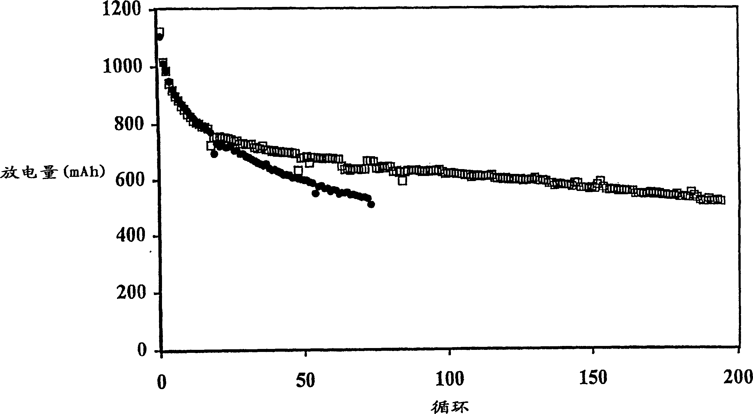
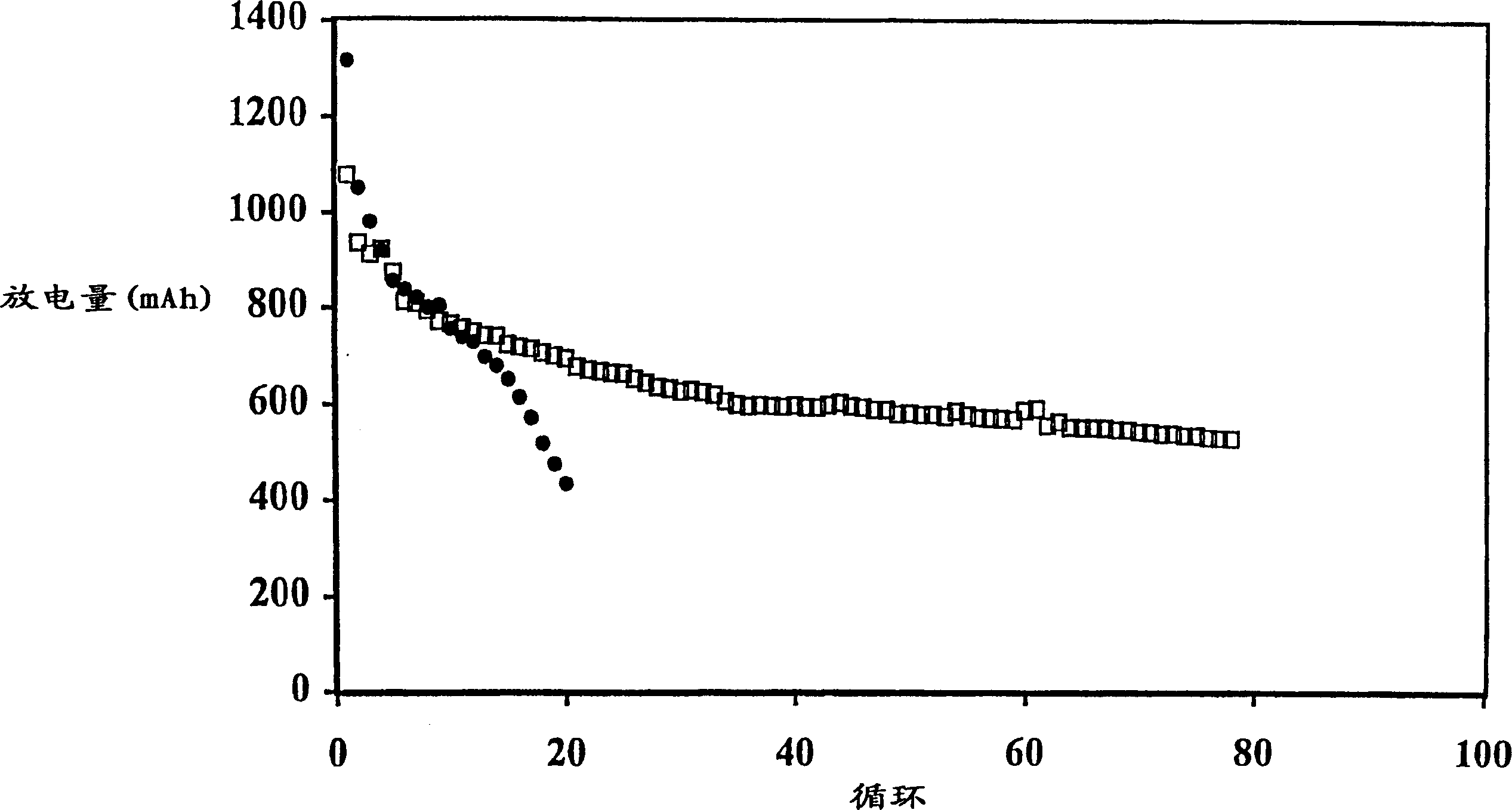
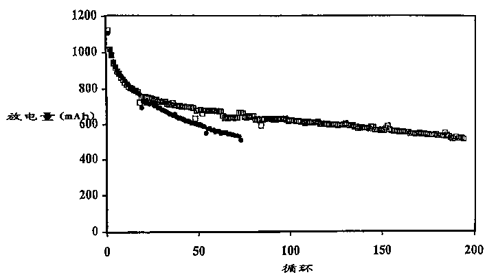
[0107] The battery produced in Example 1 was discharged to 1.5V under the condition of a discharge current of 500mA, 150mA or 50mA. The initial discharge capacity is generally about 1100mAh, and the discharge capacity of the 5th cycle is about 800-850mAh. The results of the batteries charged with the multi-step method of the present invention are shown in Table 2, and the results of the comparative batteries charged with a single step are shown in Table 1.

[0108] In Comparative Example 1, the battery was charged by the current density decreasing charging method, in which the battery was charged at a high current of 200 mA (0.25 mA / cm 2 ) to a voltage of 2.3V and then held at that voltage for 5 hours, during which time the charge current was reduced to a low level, eg 50mA.

[0109] Table 1

Relationship between battery performance and discharge-charge conditions

Comparative scale number

Discharge current

recharging curren...

Embodiment 13

[0113] table 3

[0114] The data in Table 3 illustrate that the multi-step charging method of the present invention results in less swelling of the prismatic cells. For example, Comparative Example 6 exhibits an undesirably larger overall expansion rate at 500 mAh cutoff compared to Example 2. Comparing the expansion (or FOM) per cycle, the advantages of the two-step approach are more apparent.


PUM

PropertyMeasurementUnit
Areaaaaaaaaaaa

Abstract

A method of increasing the cycle life of a discharged lithium electrochemical cell comprising (i) an anode comprising lithium; (ii) a cathode comprising an electrochemically active sulfur-containing species; (iii) an anode disposed between the anode and the cathode between liquid electrolytes; wherein said method comprises the steps of: (a) at less than 0.2mA/cm 2 Charge the battery to a battery voltage of 2.1-2.3V at an initial low charge current density; and (b) subsequently charge the battery at a rate higher than 0.2mA/cm 2 The high charge current density charges the battery to a battery voltage of at least 2.4V.

Description

field of invention [0001] The present invention is generally in the field of electrochemical cells. More specifically, the present invention relates to rechargeable lithium batteries comprising sulfur-containing cathode materials, and methods of recharging these batteries to achieve long cycle life. Background of the invention [0002] Throughout this document, various publications, patents and published patent applications are referenced. The contents of these publications, patents and published patent applications cited herein are incorporated herein to more fully describe the state of the art to which this invention pertains. [0003] There is an increasing demand for rechargeable batteries with long cycle life, fast charging, and high energy density for devices such as mobile phones, laptop computers, and other consumer electronics. Rechargeable batteries, such as those based on lithium metal anodes and solid electrochemically active sulfur-containing cathode active ma...

Claims


Application Information

Patent Timeline
IPC IPC(8): H02J7/02H01M4/38H01M4/58H01M4/60H01M10/44H02J7/00
CPCH02J7/0075H01M4/602H01M10/05H02J7/0086H01M4/5815H01M10/44H02J7/0069Y02E60/10H02J7/007182
Inventor A·B·加夫里洛夫Y·V·米克海林克
Owner SION POWER CORP
Why Eureka
Try Eureka