Non-isothermal method for fabricating hollow composite parts

A non-isothermal, hollow technology, used in household components, textiles and paper, other household appliances, etc., can solve the problems of expensive heating and cooling cycles of molds, aesthetics of substandard finished products, long durability, etc., to simplify storage and handling, The effect of fast conversions and shorter cycle times

Inactive Publication Date: 2004-04-28
EMS CHEM AG
View PDF5 Cites 12 Cited by
  • Summary
  • Abstract
  • Description
  • Claims
  • Application Information

AI Technical Summary

Problems solved by technology

The outer layer of the thermoplastic compound is not heated sufficiently above the melting temperature of the thermoplastic matrix, whereby insufficient impregnation occurs and leads to unfavorable mechanical properties and reduced surface quality
[0014] Compared with thermoplastic materials, thermoset materials have other disadvantages that are obvious for high-speed production, resulting in limited temperature capacity, substandard aesthetics of finished products, not having very long durability, not suitable for recycling and Manufacturing-related issues such as downtime due to cleanup, as well as high material handling costs and the need for secondary environmental storage
Additionally, environmental concerns arise during the manufacturing process as workers are exposed to steam, spraying, emission, etc.
Some engineered thermoset resins improve material performance at higher temperature capabilities, but come with substandard material costs associated with them
[0015] Thermoplastic materials overcome many of the disadvantages described above, but the processing techniques available are limited in cycle time due to expensive molds and the complex heating and cooling cycles of the brittle bladder material and bladder assembly with heating capabilities
In addition, high energy costs are associated with processes that require circulation or complex bladder heating systems with mold temperatures above or below the matrix melting temperature

Method used


Image

  • Non-isothermal method for fabricating hollow composite parts
  • Non-isothermal method for fabricating hollow composite parts
  • Non-isothermal method for fabricating hollow composite parts

Examples


Embodiment Construction

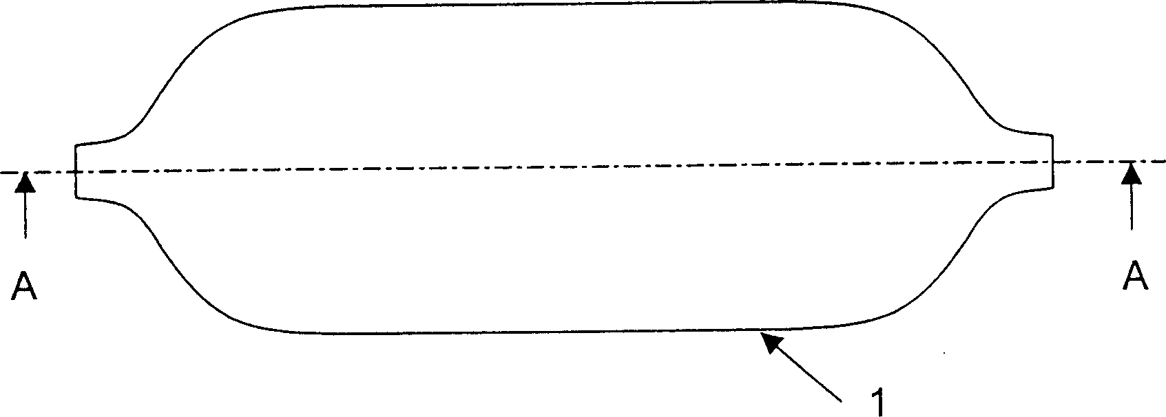
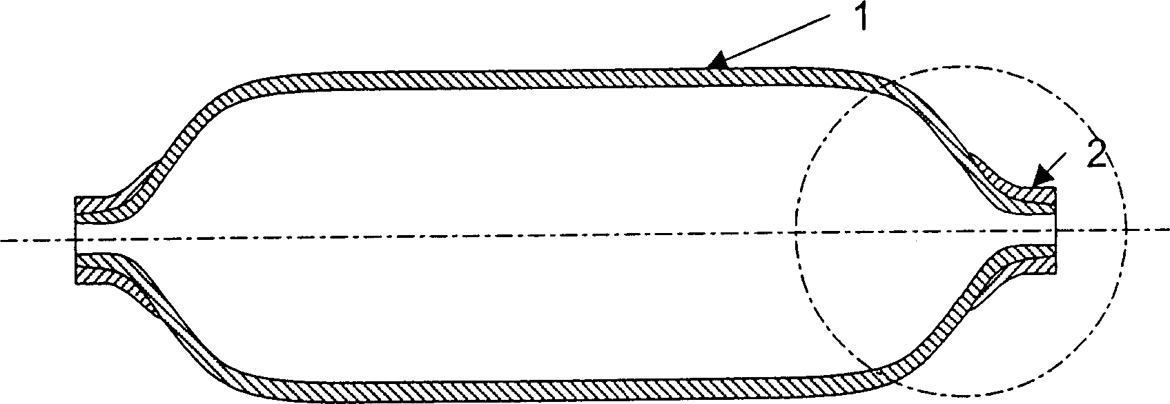
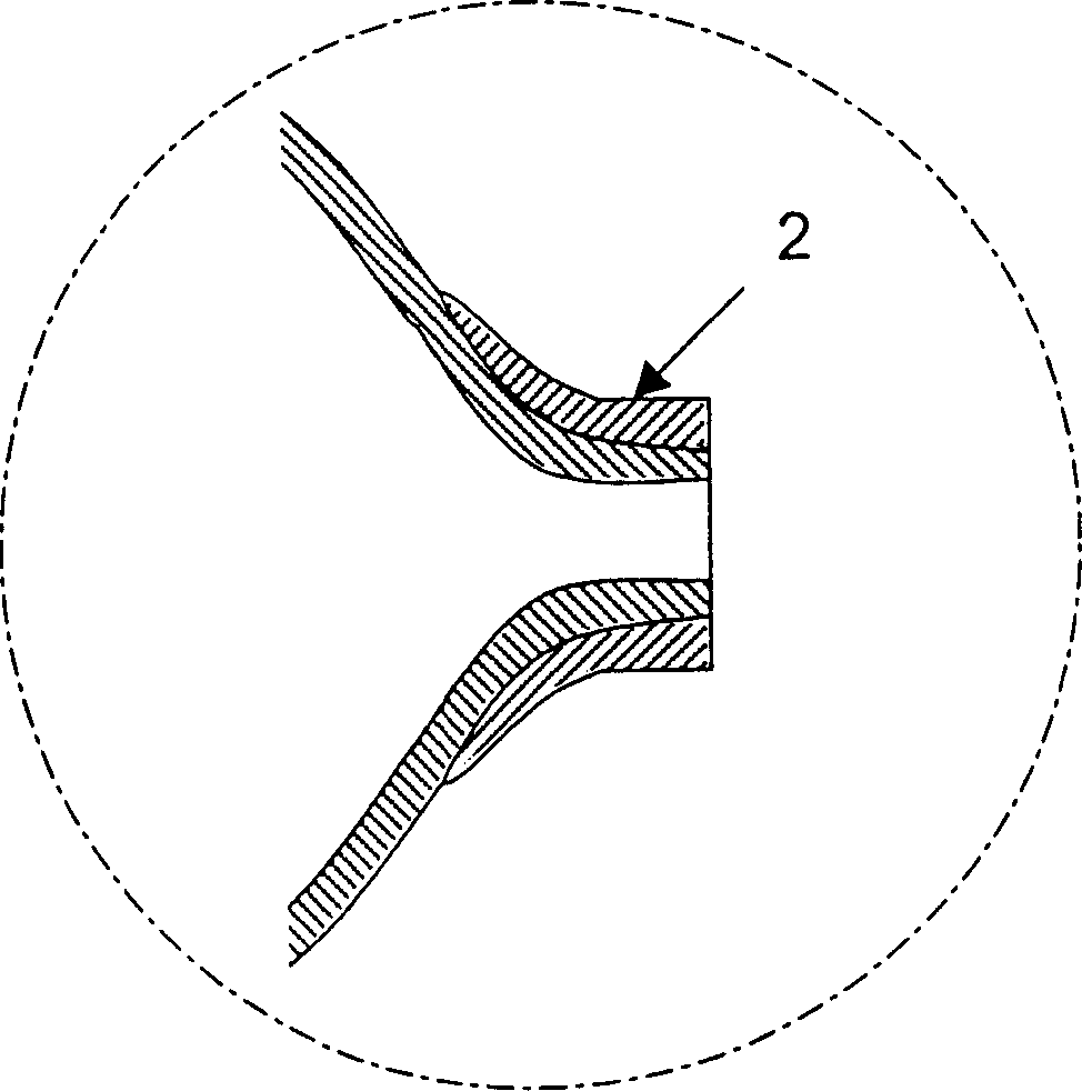
[0052] Such as figure 1 As shown, the first embodiment uses a hollow thermoplastic liner or bladder manufactured by extrusion injection molding or cast rotational molding processes. In the embodiment shown, the liner 1 or bladder is generally an elongated geometric structure that can be manufactured by extrusion injection moulding, the ends of which have one or more openings at the central axis of the part or at any other suitable location. Thus, the geometry of the bladder is not limited to rotational shapes, but any hollow thermoplastic shape capable of being manufactured by extrusion molding or cast rotational molding processes known in the art may be used. In addition to the use of thermoplastic liners1 or bladders, it is also possible to use short fiber reinforced thermoplastics or continuous fiber reinforced thermoplastics for preheating during extrusion injection molding and during non-isothermal bladder expansion molding , transfer and molding stages, the melt viscosi...


PUM

PropertyMeasurementUnit
diameteraaaaaaaaaa

Abstract

A process for making hollow composite structures of vessels which includes the steps of: A) heating a mixture of thermoplastic matrix and reinforcing fibres wrapped over a rigid or semi-rigid thermoplastic liner or bladed above the melting point of the thermoplastic composite matrix outside of a moulding tool; B) transferring the heated assembly toa mould that is maintained below the melting temperature of the thermoplastic matrix of the composite; C) closure of the mould and application of internal fluid pressure to the liner or bladder or apply pressure to the thermoplastic matrix and reinforcing fibres; D) optionally the use of a special coupling system for rapid connection of the internal pressure; E) cooling of the liner or bladder and thermoplastic matrix and reinforcing fibre assembly in contact with the cold or warm mould while consolidation of the assembly occurs; F) opening of the mould and removal of the finished assembly. Suitable thermoplastic materials for the liner / bladder and thermoplastic composite matrix material includes; polypropylene, polyamide, polyethylene, cross-linked polyethylene, polybutylene terephthalate, polyethylene terephthalate, polyoxymethylene, polyphenylene sulfide and polyetheretherketone.

Description

technical field [0001] The present invention relates to the field of manufacturing hollow composite parts, in particular space frame structures or containers, and in particular to an improved method of manufacturing space frame structures or containers and composite containers manufactured by the improved method. Background technique [0002] Hollow composite structures or pressure vessels for the storage of liquids and solids under pressure, usually space frames or tubular load-bearing assemblies, usually made of metal such as steel or aluminium, hereinafter referred to as vessels, eg pressurized gas tanks. But in recent years, the use of composite containers has become more common. Such containers are manufactured by various methods including filament winding, resin transfer molding and bladder-assisted moulding. [0003] Filament winding technology is the method of impregnating dry reinforcing fibers (such as glass or carbon fibers) with a reactive resin before being app...

Claims


Application Information

Patent Timeline
Patent Type & Authority Applications(China)
IPC IPC(8): B29C70/08B29C70/44
CPCB29L2031/7156B29C70/086B29C70/446D04C1/04D04C3/48D10B2505/02B29C70/32
Inventor 克里斯蒂安·克鲁泽帕斯卡·维约默内扬-安德斯·E·曼森马丁·D·韦克曼彼得·马斯库斯
Owner EMS CHEM AG
Why Eureka
Try Eureka