
Direct alcohol fuel cell diaphragm electrode structure and preparing process

A fuel cell and membrane electrode technology, applied in battery electrodes, structural parts, circuits, etc., can solve the problems of low mechanical strength of carbon fiber, increase of contact resistance, and influence on current collection effect, etc., to achieve integration, reduce resistance, The effect of simplifying the preparation procedure

Inactive Publication Date: 2005-03-09
DALIAN INST OF CHEM PHYSICS CHINESE ACAD OF SCI
View PDF2 Cites 23 Cited by
  • Summary
  • Abstract
  • Description
  • Claims
  • Application Information

AI Technical Summary

Problems solved by technology

[0009] The main advantage of using carbon paper or carbon cloth as the supporting material of the electrode is good electrochemical stability, but the preparation process of carbon paper or carbon cloth requires high temperature treatment and atmosphere protection, making their price higher, and compared with metal carbon The electrical conductivity of the material is two orders of magnitude lower than that of metals
[0010] On the other hand, unlike metal materials, carbon materials can be directly welded, so in the battery pack assembly process, in order to make the current collection effect better, it is necessary to extrude metal mesh or current collector plate with carbon paper and carbon fiber in carbon cloth , while carbon fiber has low mechanical strength and poor deformation resistance, so carbon fiber is often crushed under pressure, which affects the current collection effect
[0011] The current collector of the metal foam material introduced in the patent [US 2002 / 0098402 A1] collects current by contact with the diffusion layer, which also causes an increase in contact resistance

Method used


Image

  • Direct alcohol fuel cell diaphragm electrode structure and preparing process
  • Direct alcohol fuel cell diaphragm electrode structure and preparing process
  • Direct alcohol fuel cell diaphragm electrode structure and preparing process

Examples


Embodiment 1

[0050] The sintered stainless steel fiber mat is used as the diffusion layer and the current collector. The porosity is 90%, the pore diameter is 400 mesh, and the thickness is 145 μm. The preparation process is as follows:

[0051] Anode diffusion layer: Prepare a slurry containing 80% XC-72R and 20% Nafion polymer, smear it on the stainless steel fiber felt after ultrasonic vibration, and dry it to obtain a slurry containing 6mg / cm 2 Diffusion layer of XC-72R and Nafion mixture, and then flatten the diffusion layer with a certain pressure, the pressure is determined according to the size of the area, so as to ensure that the diffusion layer has no cracks.

[0052] Cathode diffusion layer: Prepare a slurry containing 80% XC-72R and 20% PTFE, smear it on the stainless steel fiber felt after ultrasonic vibration, and obtain a solution containing 6mg / cm 2 Diffusion layer of XC-72R and PTFE mixture, and then flatten the diffusion layer with a certain pressure, the pressure is det...

Embodiment 2

[0061] The sintered stainless steel fiber mat was used as the diffusion layer and current collector, with a porosity of 85%, a pore diameter of 300 mesh, and a thickness of 160 μm. Other preparation processes were the same as in Example 1.

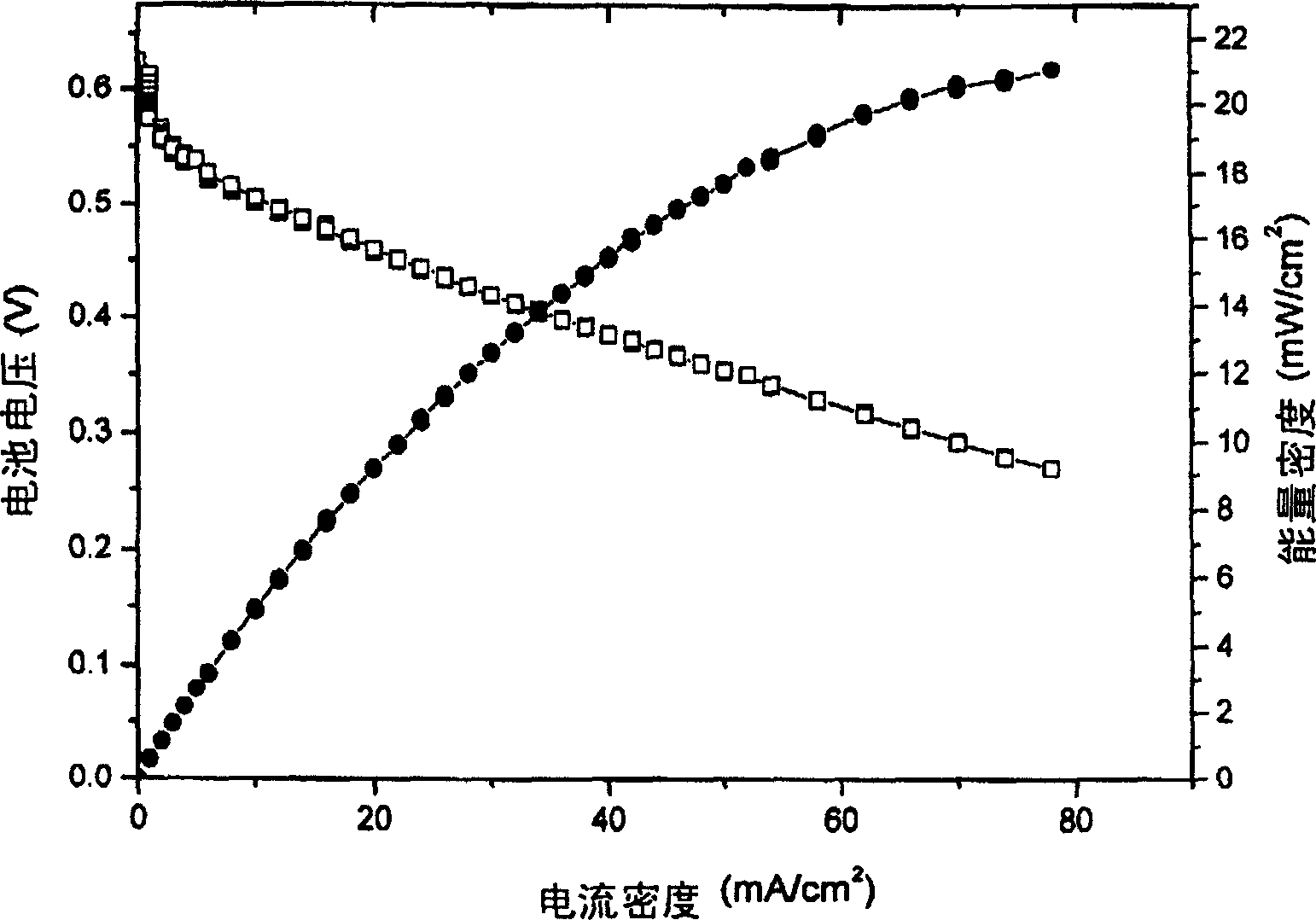
[0062] Figure 4 In the specific embodiment 2 of the present invention, the membrane electrode made of stainless steel braided mesh is under the condition of air self-breathing at room temperature, and the electrode area is 2 × 2 cm 2 single-cell discharge curve.

[0063] Put the membrane electrode obtained above into a battery testing device for testing, and its discharge curve is shown in image 3 and Figure 4 .

[0064] The working conditions of the battery are as follows:

[0065] Under normal temperature and pressure, the cathode is directly exposed to the air, and the anode is injected with 6.5ml of 1M methanol without any auxiliary equipment.

[0066] From image 3 It can be seen that the current density at 78mA / cm 2 , the p...


PUM

PropertyMeasurementUnit
Apertureaaaaaaaaaa
Thicknessaaaaaaaaaa
Apertureaaaaaaaaaa

Abstract

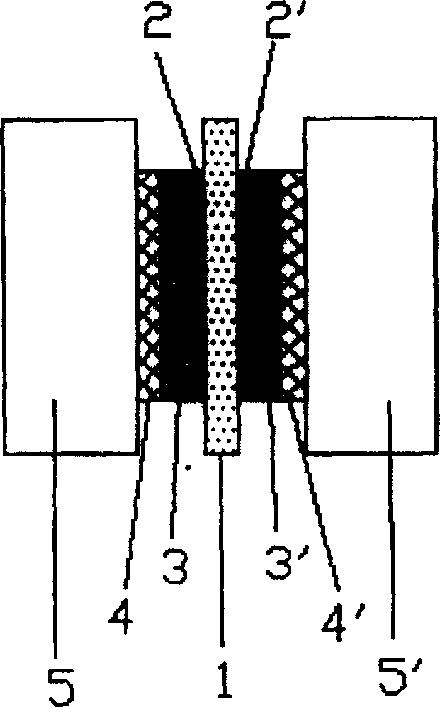
This invention relates to a structure of a fuel battery membrane electrode(MEA) and it preparing method. The said MEA is composed of a proton exchange membrane, a catalyst layer and a diffused layer applying porous metal material to combine the diffused layer with the collector.

Description

technical field [0001] The invention relates to fuel cell technology, in particular to a fuel cell membrane electrode (MEA) structure and preparation method. Background technique [0002] In recent years, with the rapid development of portable electronic products, all kinds of batteries currently on the market are expensive, have a short service life, and there are various waste disposal problems. Long-life, pollution-free energy has become an urgent need. The direct methanol fuel cell is the most promising energy source to meet these needs, because methanol has high energy density, abundant resources, and low cost. Direct Methanol Fuel Cells operating at high temperatures require a variety of auxiliary equipment, so the system is complex and not suitable for portable electronic products. Normal temperature air self-breathing direct methanol fuel cell works at normal temperature without any auxiliary equipment, but it can provide the required power with high energy convers...

Claims


Application Information

Patent Timeline
IPC IPC(8): H01M4/86H01M4/88
CPCY02E60/50
Inventor 孙公权赵锋良刘建国赵钢陈利康辛勤
Owner DALIAN INST OF CHEM PHYSICS CHINESE ACAD OF SCI
Learn More